
Motor rotor iron core magnetic steel inserting device

A motor rotor and iron core technology, which is applied in the field of motor rotor assembly, can solve the problems of limited improvement of rotor core efficiency, low degree of automation, and low production efficiency, and achieve orderly and controllable insertion rhythms, reduce The effect of reasonable production cost and mechanism design

Inactive Publication Date: 2020-05-29
SHAODONG INTELLIGENT MFG INNOVATIVE INST
View PDF6 Cites 5 Cited by
  • Summary
  • Abstract
  • Description
  • Claims
  • Application Information

AI Technical Summary

Problems solved by technology

[0003] During the manufacturing process of the above-mentioned rotor core, the magnetic steel block needs to be inserted into the corresponding position of the iron core. Previously, the magnetic steel block was inserted into the corresponding groove of the iron core mainly by manual assembly. The production efficiency of this assembly method is Low, and because there are many magnetic steel blocks on the iron core, manual operation is prone to assembly errors, resulting in a high defective rate
At present, there are some special equipments for inserting magnetic steel in the iron core, but the degree of automation of these equipment is still not high, and the improvement of the efficiency and pass rate of the magnetic steel inserting in the rotor core is still limited.

Method used


Image

  • Motor rotor iron core magnetic steel inserting device
  • Motor rotor iron core magnetic steel inserting device
  • Motor rotor iron core magnetic steel inserting device

Examples


Embodiment Construction

[0025] In order to make the technical problems, technical solutions and advantages to be solved by the present invention clearer, the following will describe in detail with reference to the drawings and specific embodiments. Apparently, the described embodiments are some, but not all, embodiments of the present invention. Based on the embodiments of the present invention, all other embodiments obtained by persons of ordinary skill in the art without making creative efforts belong to the protection scope of the present invention.

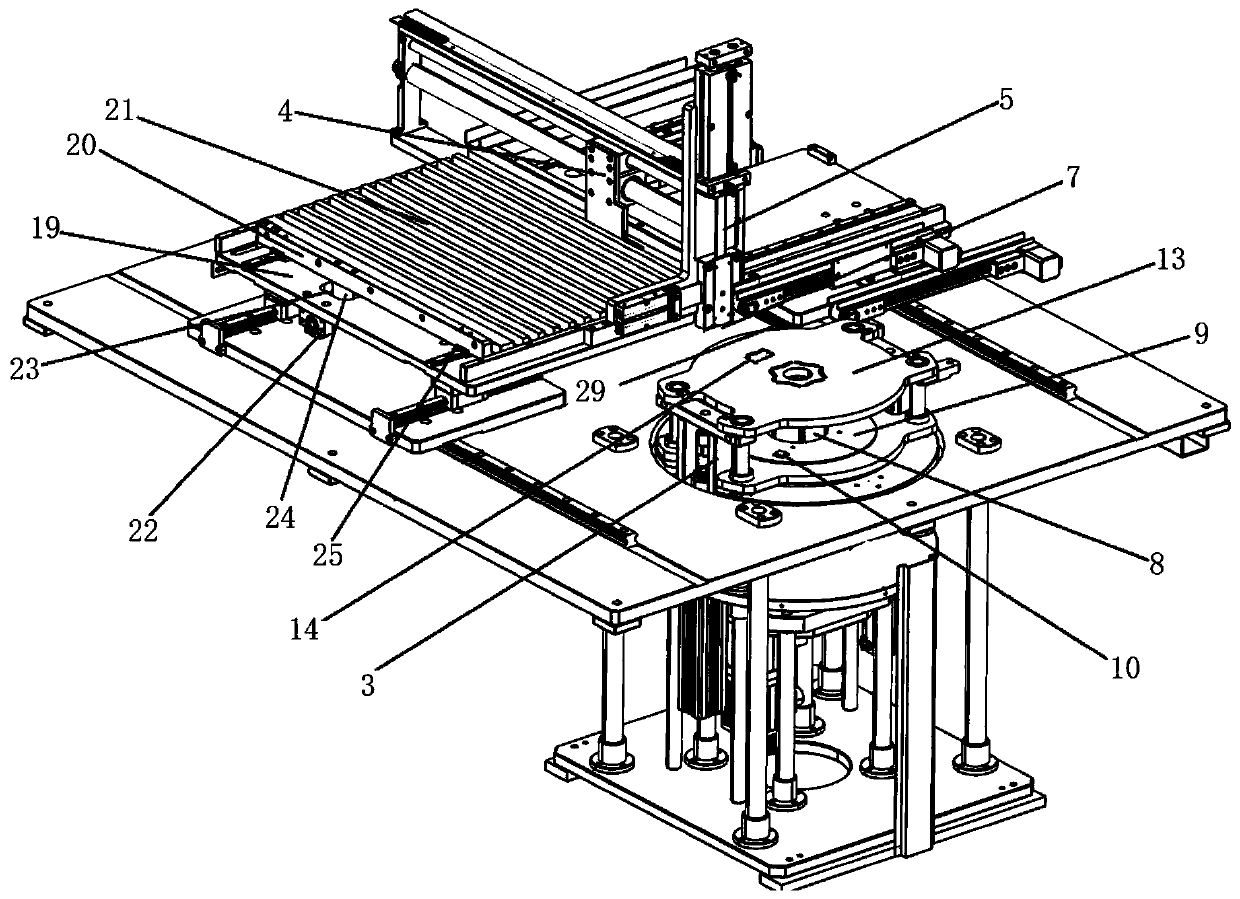
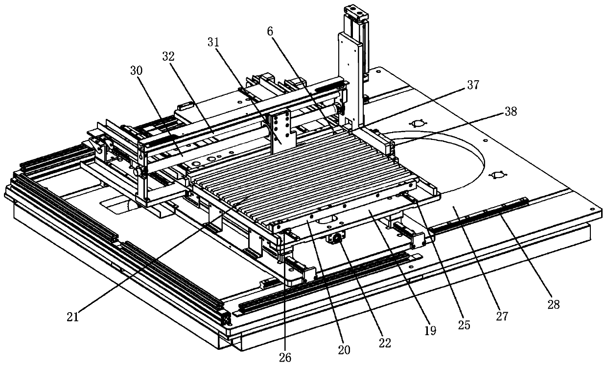
[0026] Such as Figure 5 As shown, in this embodiment, the iron core 1 is ring-shaped, and a plurality of slots 2 are arranged on the panel of the iron core 1 . at the same time as figure 1 As shown, the embodiment of the present invention provides a device for inserting magnets into the rotor iron core of a motor, including a clamping platform 3 for fixing the iron core 1 and a magnetic steel block assembly assembly, and the magnetic steel block a...


PUM


Abstract

The invention provides a motor rotor iron core magnetic steel inserting device. The device comprises a clamping platform of an iron core and a magnetic steel block assembling assembly. The magnetic steel block assembling assembly is mainly composed of a magnetic steel block feeding mechanism and a magnetic steel block inserting mechanism. The magnetic steel block feeding mechanism sequentially feeds magnetic steel blocks to a discharge port, the clamping platform drives the iron core to rotate so that each slot of the iron core sequentially reaches the discharge port, and the magnetic steel block inserting mechanism inserts the magnetic steel blocks at the discharge port into the iron core. In the invention, the slots on the iron core sequentially reach and are aligned with the discharge port in a rotating manner, and the magnetic steel block assembling assembly automatically feeds the magnetic steel blocks and accurately inserts the magnetic steel blocks into the slots so that magnetic steel inserting operation of the rotor iron core can be completed in a high-automation manner, assembling efficiency and quality are effectively improved, and production cost is reduced.

Description

technical field [0001] The invention relates to the technical field of motor rotor assembly, in particular to a device for inserting magnetic steel into the iron core of a motor rotor. Background technique [0002] The permanent magnet motor is usually composed of a rotor and a stator. The common rotor core adopts the structure of an inserted magnetic steel block, and a magnetic steel block made of permanent magnet material is inserted in the rotor core as the rotating mechanism of the motor. Interacting with the rotating magnetic field generated by the stator, causes the rotor to rotate and produce the output of the motor. [0003] During the manufacturing process of the above-mentioned rotor core, the magnetic steel block needs to be inserted into the corresponding position of the iron core. Previously, the magnetic steel block was inserted into the corresponding groove of the iron core mainly by manual assembly. The production efficiency of this assembly method is Low, a...

Claims


Application Information

Patent Timeline
IPC IPC(8): H02K15/03H02K15/02
CPCH02K15/024H02K15/03
Inventor 邓余民康文杰单常清
Owner SHAODONG INTELLIGENT MFG INNOVATIVE INST
Learn More