
Moving beam type gantry machining center structure

A machining center and gantry technology, applied in metal processing equipment, metal processing machinery parts, manufacturing tools, etc., can solve problems such as imperfect design of force structure and support distribution, structural failure, high center of gravity weight distribution, etc., to achieve stability and high efficiency The effect of long-term working operation, eliminating structural deficiencies and defects, and maintaining machining accuracy

Pending Publication Date: 2021-01-05
江门市精钻数控科技有限公司
View PDF0 Cites 0 Cited by
  • Summary
  • Abstract
  • Description
  • Claims
  • Application Information

AI Technical Summary

Problems solved by technology

[0002] The moving beam type gantry machining center is a large machine tool equipment. Compared with the fixed beam type gantry, the beam of the moving beam type gantry needs to move while carrying the high weight mechanism. At the same time, the mechanism on the beam is also movable. The moving mechanism, so the moving beam type gantry machining center is a structure with a high center of gravity and uneven weight distribution, while the existing moving beam type gantry machining center has an unreasonable moving connection structure, and the design of the force structure and support distribution is not perfect, making The mobile connection structure is prone to severe stress on the weak supporting parts, which will lead to structural failure soon after long-term application

Method used


Image

  • Moving beam type gantry machining center structure
  • Moving beam type gantry machining center structure

Examples


Embodiment Construction

[0018] The specific implementation manners of the present invention will be further described in detail below in conjunction with the accompanying drawings and embodiments. The following examples are used to illustrate the present invention, but are not intended to limit the scope of the present invention.

[0019] In the description of the present invention, it should be understood that unless otherwise specified and limited, the terms "installation", "connection" and "connection" used in the present invention should be interpreted in a broad sense, for example, it can be a fixed connection, or It can be a detachable connection or an integral connection; it can be a mechanical connection or an electrical connection; it can be a direct connection or an indirect connection through an intermediary, and it can be the internal communication of two components. Those of ordinary skill in the art can understand the specific meanings of the above terms in the present invention in spec...


PUM


Abstract

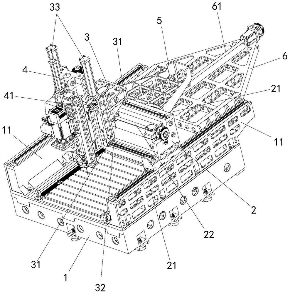
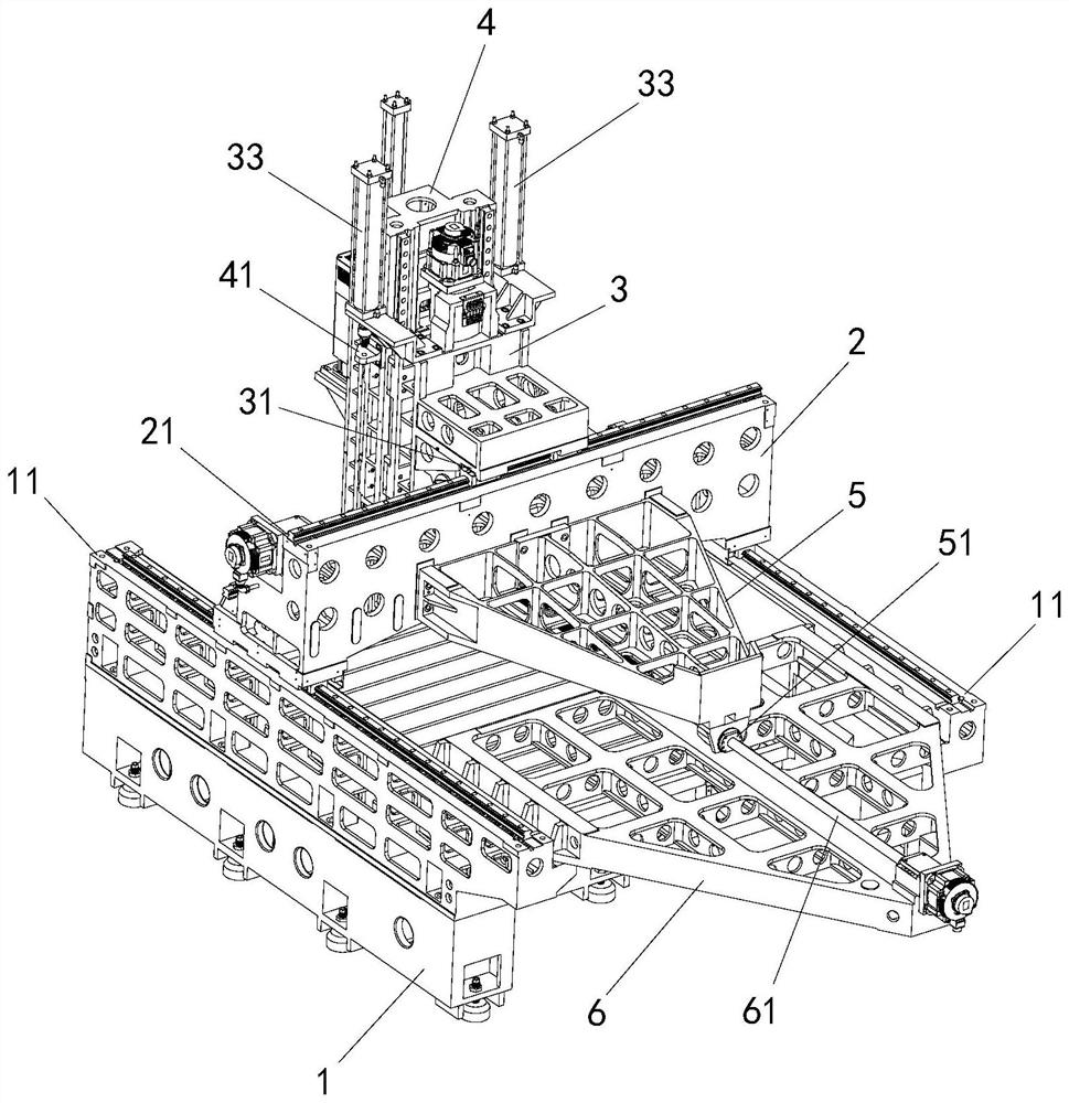
The invention relates to the technical field of machine tools, and discloses a moving beam type gantry machining center structure. The moving beam type gantry machining center structure comprises a base, a cross beam, a slide carriage and a slide plate, the cross beam is movably mounted on the base, the slide carriage is movably mounted on the cross beam, the slide plate is movably mounted on thefront side of the slide carriage, the cross beam is provided with two or more bearing faces which are distributed in a front-back stepped mode and face upwards, the bearing faces are provided with sliding rails which extend leftwards and rightwards, the slide carriage is provided with connecting parts which correspond to the bearing faces correspondingly and are distributed in a stepped mode, andthe connecting parts face downwards and are provided with sliding blocks; and the sliding rails on the bearing surfaces are slidably connected with the sliding blocks on the connecting parts. Comparedwith the prior art, according to the moving beam type gantry machining center structure, structural deficiencies and defects of an existing moving beam gantry are overcome, a mechanism can work and operate more stably and efficiently for a long time, and the machining precision is effectively kept.

Description

technical field [0001] The invention relates to the technical field of machine tools, in particular to a structure of a moving beam type gantry machining center. Background technique [0002] The moving beam type gantry machining center is a large machine tool equipment. Compared with the fixed beam type gantry, the beam of the moving beam type gantry needs to move while carrying the high weight mechanism. At the same time, the mechanism on the beam is also movable. The moving mechanism, so the moving beam type gantry machining center is a structure with a high center of gravity and uneven weight distribution, while the existing moving beam type gantry machining center has an unreasonable moving connection structure, and the design of the force structure and support distribution is not perfect, making The mobile connection structure is prone to severe stress on the weak supporting parts, which will lead to structural failure soon after long-term application. Contents of th...

Claims


Application Information

Patent Timeline
IPC IPC(8): B23Q1/01B23Q1/25
CPCB23Q1/015B23Q1/25
Inventor 雷德武
Owner 江门市精钻数控科技有限公司
Learn More