Food processor with long service life

A technology for food processing machines and bases, applied in applications, kitchen utensils, home utensils, etc., can solve the problems of shortening the durability and service life of the feeding cover, affecting the normal use and loosening of the feeding cover, and improving the user experience and satisfaction. degree, noise reduction, noise reduction effect

Pending Publication Date: 2020-06-02
JOYOUNG CO LTD
View PDF5 Cites 0 Cited by
  • Summary
  • Abstract
  • Description
  • Claims
  • Application Information

AI Technical Summary

Problems solved by technology

[0003] The existing feeding cover generally includes a baffle, a gripping portion located at the upper end of the baffle, and an insertion portion located at the lower end of the baffle and extending into the feeding channel, and the insertion portion and the baffle are connected together through secondary fixing. When the processing machine is working and exhausting, the gas will pass through the feeding cover. After a long time, the gas will corrode the joint between the insertion part and the baffle, making the insertion part and the baffle loose, affecting the normal use of the feeding cover and shortening Improve the durability and service life of the feeding cover

Method used


Image

  • Food processor with long service life
  • Food processor with long service life
  • Food processor with long service life

Examples


Embodiment 1

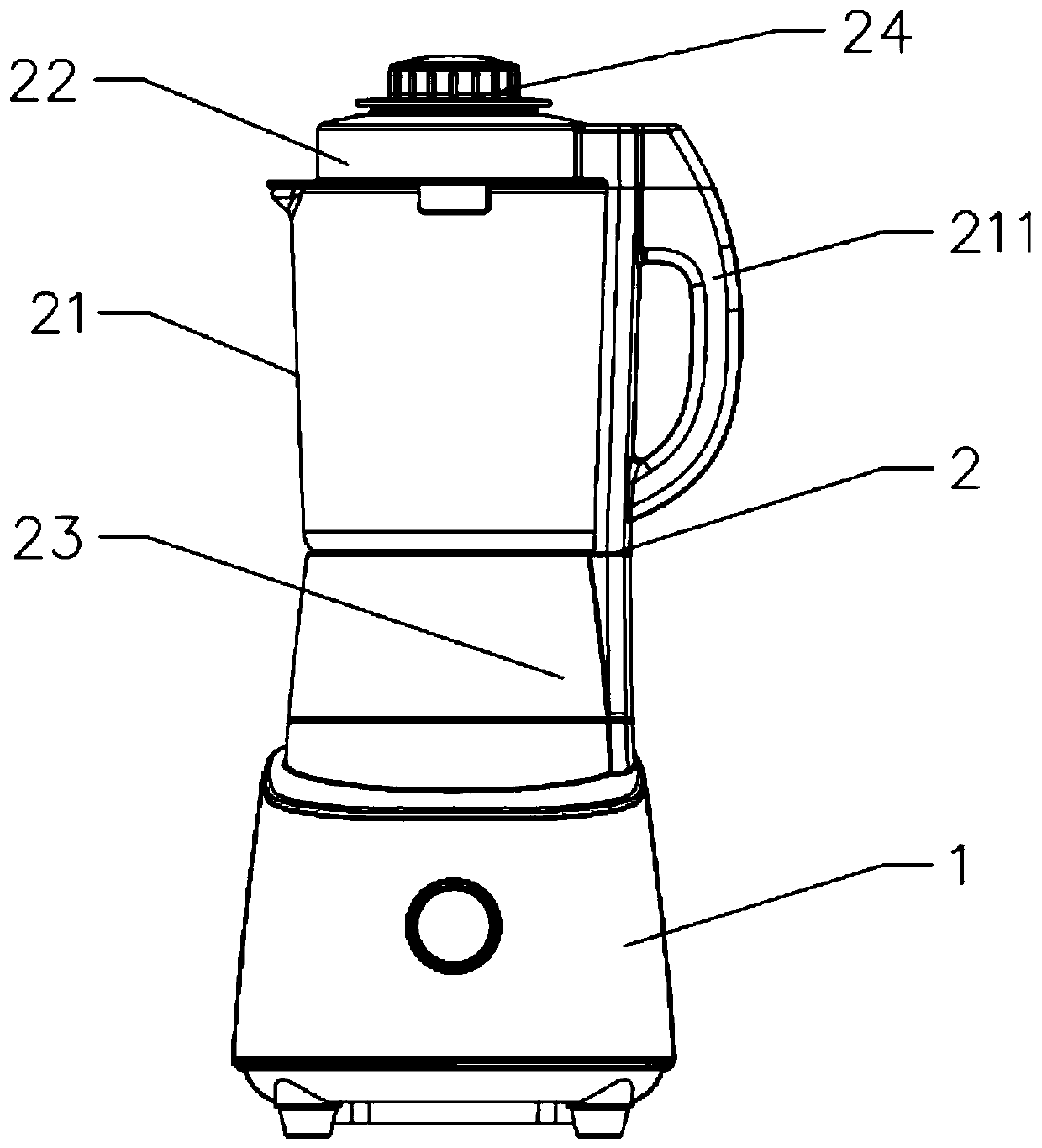
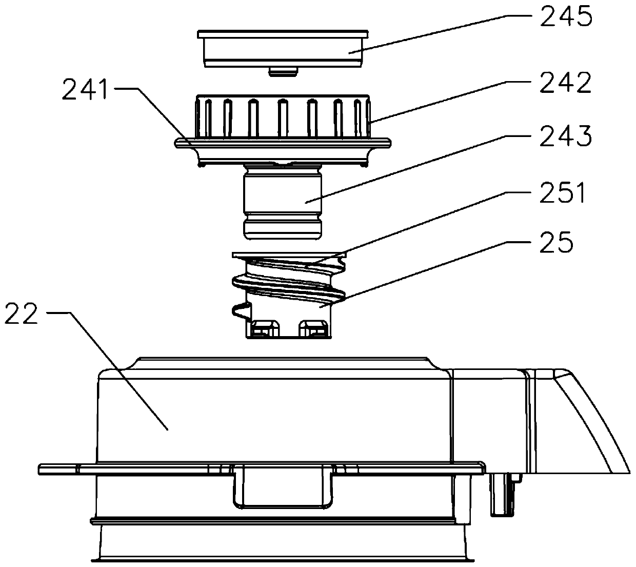
[0045] Such as Figures 1 to 10 As shown, the present invention provides a food processor with a long service life, including a machine base 1 and a stirring cup 2, a motor (not shown in the figure) and a control panel (not shown in the figure) are arranged in the machine base 1, The stirring cup 2 includes a cup body 21 and a cup cover 23 covering the top of the cup body 21. The side wall of the cup body 21 is provided with a handle 211, and a cup holder 23 is provided below the cup body 21. The stirring cup 2 is detachably installed through the cup holder 23. Above the machine base 1, a feeding channel 221 is provided on the cup cover 22, and a feeding cover 24 is provided at the feeding channel 221. The feeding cover 24 includes a baffle 241, a gripping portion 242 positioned at the upper end of the baffle 241 and a lower end of the baffle 241. and extend into the insertion part 243 in the feeding channel 221.

[0046] In this embodiment, the insertion portion 243 is seale...

Embodiment 2

[0063]The difference between this embodiment and the first embodiment lies in that the setting positions of the sealing plates are different.

[0064] In this example, if Figures 11 to 12 As shown, the sealing plate 244 is set at the upper port 2431, so that the insertion part 243 is closed, and the upper surface of the sealing plate 244 is not set higher than the upper port 2431 of the insertion part 243. The connection between the plates is fixed, and it can well prevent the gas from entering the joint between the insertion part and the baffle, so as to avoid loosening between the insertion part and the baffle, so as to ensure the normal use of the feeding cover.

[0065] The structures and beneficial effects of other parts not described are the same as those in Embodiment 1, and will not be repeated here.

Embodiment 3

[0067] The difference between this embodiment and the first embodiment lies in that the setting positions of the sealing plates are different.

[0068] In this example, if Figures 13 to 14 As shown, the sealing plate 244 is arranged in the insertion portion 243, the sealing plate 244 is located between the upper port 2431 and the lower port 2432, so that the insertion portion 243 is closed, and the sealing plate 244 is specifically located in the middle of the upper port 2431 and the lower port 2432 Position, so that although the gas can enter the insertion part, it will be blocked by the sealing plate and will not rise further to the upper port. This can also prevent the gas from entering the connection between the insertion part and the baffle and prevent the two from falling off.

[0069] The structures and beneficial effects of other parts not described are the same as those in Embodiment 1, and will not be repeated here.


PUM


Abstract

The invention provides a food processor with long service life. The food processor comprises a machine base and a stirring cup, and a motor and a control panel are arranged in the machine base. The stirring cup comprises a cup body and a cup cover; a feeding channel is formed in the cup cover; a feeding cover is arranged at the feeding channel; the feeding cover comprises a baffle plate, a holdingpart and an inserting part; the inserting part is closed, the baffle plate is a plastic baffle plate, the inserting part is a metal inserting part; the inserting part is embedded in the baffle plate,a soft rubber sleeve sleeves outside the inserting part; a soft rubber screw is arranged on the outer side wall of the soft rubber sleeve; a spiral exhaust channel is formed by the flexible glue spiral and the inner side wall of the feeding channel; the lower end of the exhaust channel is communicated with the interior of the cup body, and an exhaust gap is formed between the upper end of the feeding cover and the upper end of the feeding channel, so that gas cannot enter the inserting part and cannot enter the connection matching position of the inserting part and the baffle plate, and the connection matching position of the inserting part and the baffle plate cannot be corroded.

Description

technical field [0001] The invention relates to the field of food processing machines, in particular to a food processing machine with long service life. Background technique [0002] Existing food processing machines generally include a machine base, a motor located in the machine base, and a stirring cup. A pulverizer driven by a motor is arranged in the stirring cup. The stirring cup generally includes a cup body and a cup cover. In order to facilitate feeding in the middle, Generally, there is a feeding channel in the center of the cup cover, and a feeding cover is set at the feeding channel, and an exhaust gap is provided at the joint between the feeding cover and the feeding channel to ensure the internal and external pressure balance of the cup. [0003] The existing feeding cover generally includes a baffle, a gripping portion located at the upper end of the baffle, and an insertion portion located at the lower end of the baffle and extending into the feeding channel...

Claims


Application Information

Patent Timeline
Patent Type & Authority Applications(China)
IPC IPC(8): A47J43/046A47J43/07
CPCA47J43/046A47J43/0716
Inventor 王旭宁刘同亮郭先炳
Owner JOYOUNG CO LTD
Why Eureka
Try Eureka