Supercharge Your Innovation With Domain-Expert AI Agents!

Filtering separating device for bioengineering

A filtration separation and bioengineering technology, applied in separation methods, precipitation separation, grain processing, etc., can solve the problems of impure extraction of biological samples, affecting the accuracy of experimental results, and residual biological samples.

Active Publication Date: 2020-06-02
广西自贸区见炬科技有限公司 +1
View PDF7 Cites 0 Cited by
  • Summary
  • Abstract
  • Description
  • Claims
  • Application Information

AI Technical Summary

Problems solved by technology

[0002] In the process of biological experimental detection, when the organisms are separated by layers with upper and lower structures, to obtain the lower layer of biological samples, it is necessary to probe the test tube from the upper layer of biological samples and suck them out. Although the middle section is intercepted for experimental detection, the lower layer There will still be a small amount of upper biological samples in the biological samples, which will affect the accuracy of the experimental results. Therefore, the separation and filtration of biological samples needs to be further explored. The current filtration and separation equipment for bioengineering has the following defects:
[0003] The existing bioengineering filtration and separation equipment solves the problem that the test tube is inserted from the upper biological sample and the lower biological sample is taken out, which will cause the sample to contain the upper biological sample by extracting the upper biological sample from the top and the lower biological sample from the bottom. The problem with the sample is that after the extraction of the biological sample is completed, the method of clearing the biological sample from the extraction port of the lower layer will leave some biological samples remaining, resulting in impure extraction of the next biological sample

Method used


Image

  • Filtering separating device for bioengineering
  • Filtering separating device for bioengineering
  • Filtering separating device for bioengineering

Examples


Embodiment 1

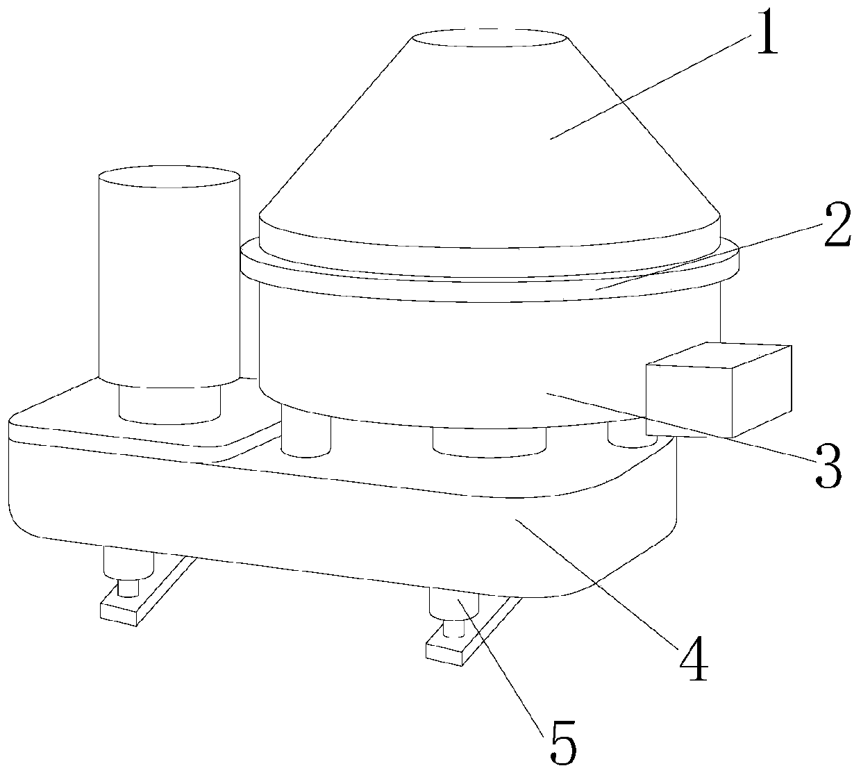
[0029] see Figure 1-Figure 7 , the present invention provides a filtration and separation device for bioengineering, the structure of which includes a separation chamber 1, a connecting ring 2, an inactivation device 3, a fixing seat 4, and a supporting foot 5, and the separation chamber 1 is installed on the fixing seat 4, so that The bottom of the fixed seat 4 is provided with a supporting foot 5, and the supporting foot 5 is provided with two, and is set up in a symmetrical structure. Inside, the connecting ring 2 is set up in a concentric ring shape, and the connecting ring 2 is mechanically connected to the outer wall of the separation chamber 1;

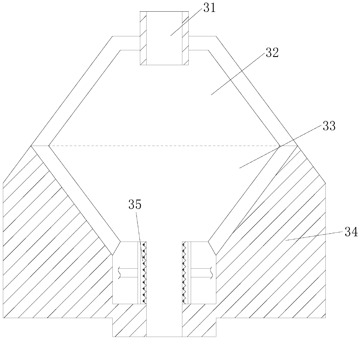
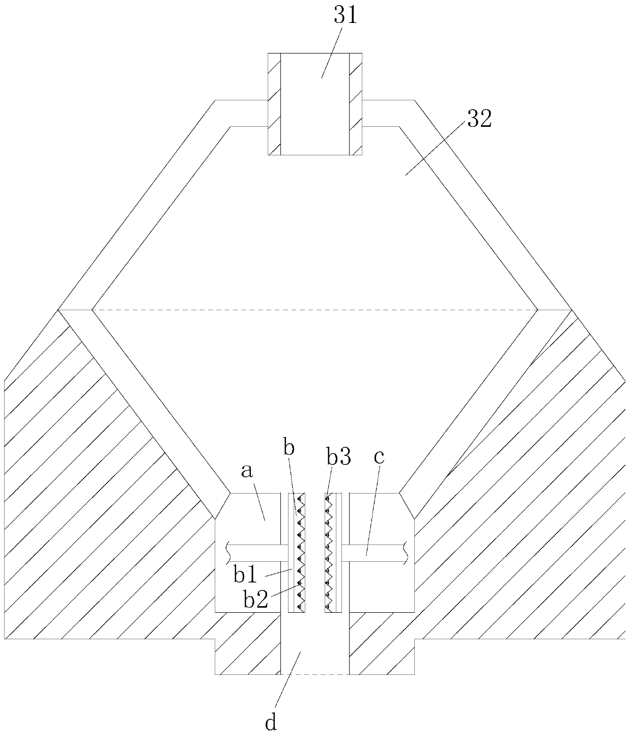
[0030] Described inactivation device 3 is made of upper outlet 31, upper chamber 32, lower chamber 33, wall layer 34, lower outlet 35, and described upper outlet 31 is connected with upper chamber 32, and between described upper chamber 32, lower chamber 33 The upper chamber 32 and the lower chamber 33 have the same structure...

Embodiment 2

[0041] see Figure 1-Figure 4 , Figure 7 , the present invention provides a filtration and separation device for bioengineering, the structure of which includes a separation chamber 1, a connecting ring 2, an inactivation device 3, a fixing seat 4, and a supporting foot 5, and the separation chamber 1 is installed on the fixing seat 4, so that The bottom of the fixed seat 4 is provided with a supporting foot 5, and the supporting foot 5 is provided with two, and is set up in a symmetrical structure. Inside, the connecting ring 2 is set up in the shape of a concentric ring, and the connecting ring 2 is mechanically connected to the outer wall of the separation chamber 1; The lower outlet 35 is formed, the upper outlet 31 is connected with the upper cavity 32, and the upper cavity 32 and the lower cavity 33 are connected. The upper cavity 32 and the lower cavity 33 have the same structure and are relatively set up in an up and down structure. The lower chamber 33 communicates...


PUM


Abstract

The invention discloses a filtering separating device for bioengineering. The device structurally comprises a separating bin, a connecting ring, an inactivation device, a fixed base and supporting feet. The separation bin is mounted on the fixed base, the two supporting feet are mounted on the bottom of the fixed base, and are arranged to be of a symmetric structure, the supporting feet are mechanically welded with the fixed base, and the inactivation device is mounted in the separating bin. The device has the beneficial effects that through outer mechanical force, two movable rods are controlled to oppositely and inconsistently move, opposite and inconsistent motion control between a sub grinding head and a main grinding head can be achieved, biological sample residue remaining on the inner wall of an output pipe is ground, biological sample residue between the sub grinding head and the main grinding head gets close to along with the sub grinding head and the main grinding head, a grinding needle is embedded with an embedded groove in the end, away from a fixed groove, of a fixed rod, smashing of the biological sample residue is more thorough, and the reaction between remaining biological samples and next separated biological samples can be avoided.

Description

technical field [0001] The invention relates to the field of biological filtration, in particular to a filtration and separation device for bioengineering. Background technique [0002] In the process of biological experimental detection, when the organisms are separated by layers with upper and lower structures, to obtain the lower layer of biological samples, it is necessary to probe the test tube from the upper layer of biological samples and suck them out. Although the middle section is intercepted for experimental detection, the lower layer There will still be a small amount of upper biological samples in the biological samples, which will affect the accuracy of the experimental results. Therefore, the separation and filtration of biological samples needs to be further explored. The current filtration and separation equipment for bioengineering has the following defects: [0003] The existing bioengineering filtration and separation equipment solves the problem that the...

Claims


Application Information

Patent Timeline
IPC IPC(8): B02C1/00B02C23/00B01D21/00B01D21/24
CPCB01D21/0006B01D21/24B02C1/00B02C23/00
Inventor 马玉春
Owner 广西自贸区见炬科技有限公司
Features
  • R&D
  • Intellectual Property
  • Life Sciences
  • Materials
  • Tech Scout
  • Unparalleled Data Quality
  • Higher Quality Content
  • 60% Fewer Hallucinations
Learn More