Motor shell cleaning equipment for industrial motor machining

A technology for industrial motors and cleaning equipment, which is applied in the direction of cleaning methods using tools, cleaning methods using liquids, cleaning methods and utensils, etc., can solve the problems of accumulation of dust and dirt, affecting the normal use of the motor, and inconvenient cleaning of the motor casing. It can achieve the effect of good cleaning effect and convenient cleaning of the motor casing.

Active Publication Date: 2020-06-02
上海雷祥压铸有限公司
View PDF10 Cites 8 Cited by
  • Summary
  • Abstract
  • Description
  • Claims
  • Application Information

AI Technical Summary

Problems solved by technology

This device can only clean the outer wall of the motor casing, and the motor will accumulate dust and dirt inside after a long time of use, which will affect the normal use of the moto

Method used


Image

  • Motor shell cleaning equipment for industrial motor machining
  • Motor shell cleaning equipment for industrial motor machining
  • Motor shell cleaning equipment for industrial motor machining

Examples


specific Embodiment approach 1

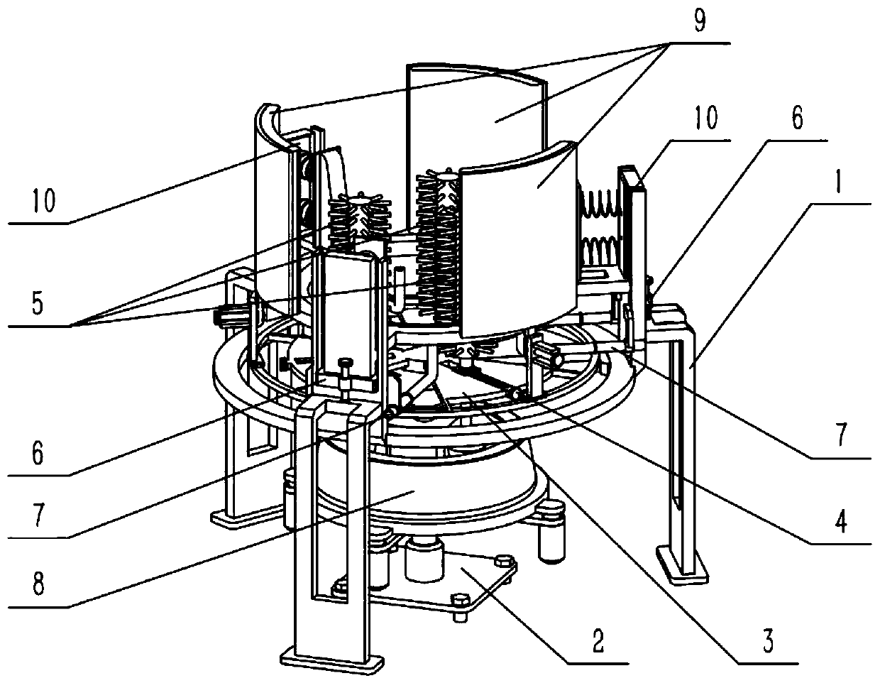
[0040] Combine below Figure 1-14 Describe this embodiment, a motor housing cleaning equipment for industrial motor processing, including a main frame 1 and a positioning structure 10, the positioning structure 10 is provided with three, and the three positioning structures 10 are uniformly arranged on the center of the main frame 1 in the axial direction In the upper part, the motor shell cleaning equipment for industrial motor processing also includes a bottom support mechanism 2, a drive mechanism 3, a radius adjustment mechanism 4, a cleaning structure 5, a connecting frame 6, a water spray pipe 7, a friction transmission ring seat 8 and an outer wall cleaning structure 9 , the lower end of the bottom supporting mechanism 2 is fixedly connected to the ground, the lower end of the driving mechanism 3 is fixedly connected to the bottom supporting mechanism 2, and its upper end is slidably connected to the center of the upper part of the main body frame 1. The radius adjustmen...

specific Embodiment approach 2

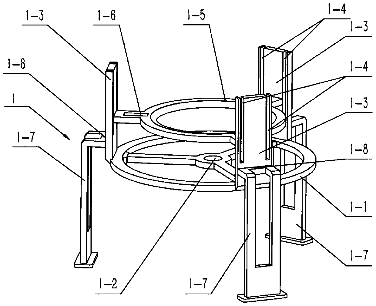
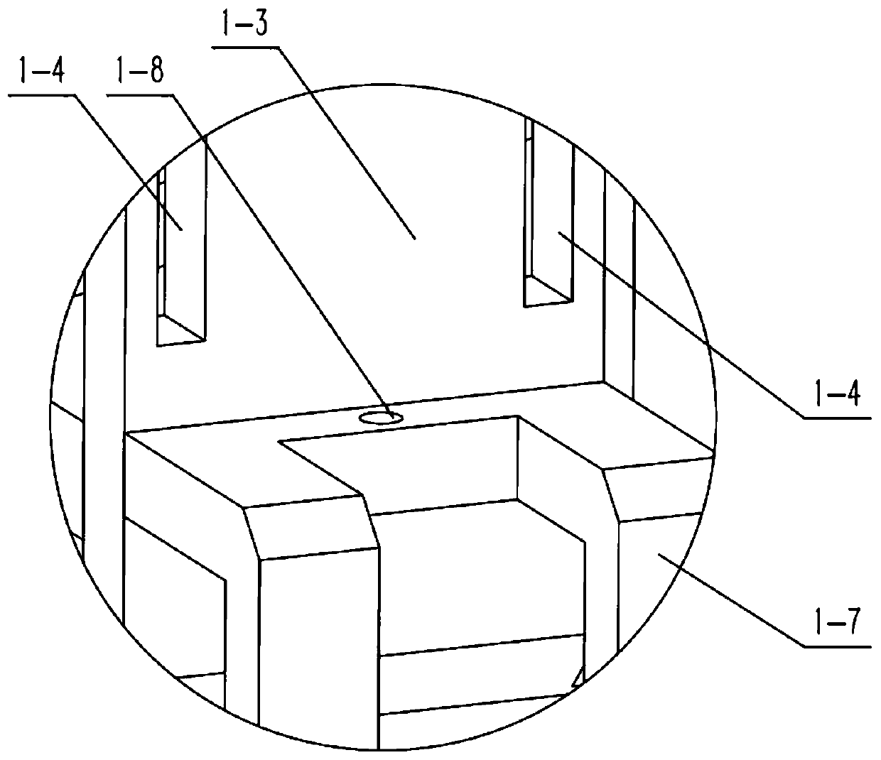
[0043] Combine below Figure 1-14 This embodiment will be described. This embodiment will further describe the first embodiment. The main body frame 1 includes a bottom ring 1-1, a hole I1-2, a vertical plate 1-3, a chute I1-4, an upper ring 1-5, Sliding holes 1-6, legs 1-7 and holes II 1-8, holes I 1-2 are provided in the middle of the bottom ring 1-1, three vertical plates 1-3 are provided, and three vertical plates 1- 3. The circumferential direction is evenly and fixedly connected to the bottom ring 1-1, and two chute I1-4 are symmetrically arranged on each vertical plate 1-3, and the upper ring 1-5 is fixedly connected to the three Between the vertical boards 1-3, three sliding holes 1-6 are evenly arranged in the peripheral direction of the sides, and three supporting legs 1-7 are provided, and the three supporting legs 1-7 are respectively fixedly connected to the three vertical On the board 1-3, a hole II1-8 is provided at the center of the upper part of each leg 1-7;...

specific Embodiment approach 3

[0046] Combine below Figure 1-14 Describe this embodiment, this embodiment will further explain the first embodiment, the bottom support mechanism 2 includes a bottom plate 2-1, a hydraulic rod 2-2, a cross support plate 2-3, a placement cylinder 2-4 and an electric telescopic rod 2 -5, the hydraulic rod 2-2 is fixedly connected to the bottom plate 2-1, the cross support plate 2-3 is fixedly connected to the upper end of the hydraulic rod 2-2, and the placement cylinder 2-4 is set There are four, four placement tubes 2-4 are respectively fixedly connected to the four ends of the cross support plate 2-3, and each electric telescopic rod 2-5 is provided with an electric telescopic rod 2-5;

[0047] The lower end of the driving mechanism 3 is fixedly connected to the middle part of the upper end of the cross support plate 2-3, the lower end of the friction transmission ring seat 8 is fixedly connected to a base 8-1, and the base 8-1 is fixedly connected to the The upper ends of...


PUM


Abstract

The invention relates to the technical field of industrial cleaning equipment, in particular to motor shell cleaning equipment for industrial motor machining. When the motor shell cleaning equipment is used, a motor shell can be fixed in the motor shell cleaning equipment through a main body frame and a positioning structure, and the relative position of each cleaning structure is adjusted througha radius adjusting mechanism and a bottom supporting mechanism, so that the best cleaning effect is achieved; the relative position of a friction transmission ring seat is adjusted, so that the friction transmission ring seat, the lower part of each cleaning structure and the inner wall of the friction transmission ring seat are in a good friction transmission state, and a driving mechanism rotates forwards and backwards in a reciprocating manner while driving the cleaning structures to revolve forwards and backwards in a reciprocating manner, so that the cleaning effect is better; and a water spraying pipe is connected with a water pump, the water spraying pipe can spray water into the motor shell through the water pump to assist the cleaning structures in cleaning the inner wall of themotor shell, and the driving mechanism drives outer wall cleaning structures to clean the outer wall of the motor shell at the same time. According to the equipment, the motor shell is convenient to clean, and the cleaning effect is good.

Description

technical field [0001] The invention relates to the technical field of industrial cleaning equipment, in particular to a cleaning equipment for motor shells used in industrial motor processing. Background technique [0002] For example, the publication number is CN109225984A, a kind of motor housing cleaning equipment for industrial motor processing, including a base, the top of the base is fixedly connected with a top plate through a support frame, the top of the top plate is movably connected with a rotating motor through a rotating rod, and the bottom of the rotating rod is fixedly connected through a hydraulic rod There is a positioning box, the bottom of the positioning box is movably connected with the inner wall of the casing, the bottom of the cleaning diversion box is fixedly connected with a water outlet pipe, the bottom of the water outlet pipe is fixedly connected with a water storage tank, and the middle part of the inner cavity of the water storage tank is fixed...

Claims


Application Information

Patent Timeline
IPC IPC(8): B08B3/02B08B1/04B08B13/00
CPCB08B1/002B08B1/04B08B3/02B08B13/00
Inventor 张丽燕
Owner 上海雷祥压铸有限公司
Why Eureka
Try Eureka