
Edge trimming machine and method for trimming the edge of a workpiece by using the same

A flashing machine and flashing technology, which is applied to the attachments of shearing machines, shearing devices, manufacturing tools, etc., can solve the problem that manual shearing of flashing is difficult to ensure the uniformity of shearing flashes, and affects the car stopper hub frame. The quality of shearing flash and the poor working environment can achieve the effect of easy tool setting and tool change, saving time for loading and unloading, and avoiding empty cutting.

Active Publication Date: 2021-01-29
LUSHAN COLLEGE OF GUANGXI UNIV OF SCI & TECH +1
View PDF6 Cites 0 Cited by
  • Summary
  • Abstract
  • Description
  • Claims
  • Application Information

AI Technical Summary

Problems solved by technology

[0002] At present, the work of cutting the flash of the hub frame of the automobile stopper is manual operation, the work efficiency is extremely low, and the working environment is relatively harsh. It is difficult to ensure the uniformity of the cut flash by manual cutting of the flash. The quality of the shearing flash of the hub frame of the automobile stopper

Method used


Image

  • Edge trimming machine and method for trimming the edge of a workpiece by using the same
  • Edge trimming machine and method for trimming the edge of a workpiece by using the same
  • Edge trimming machine and method for trimming the edge of a workpiece by using the same

Examples


Embodiment Construction

[0040]The following will clearly and completely describe the technical solutions in the embodiments of the present invention with reference to the accompanying drawings in the embodiments of the present invention. Obviously, the described embodiments are only some, not all, embodiments of the present invention. Based on the embodiments of the present invention, all other embodiments obtained by persons of ordinary skill in the art without making creative efforts belong to the protection scope of the present invention.

[0041] It should be noted that when a component is said to be "fixed" to another component, it can be directly on the other component or there can also be an intervening component. When a component is said to be "connected" to another component, it may be directly connected to the other component or there may be intervening components at the same time. When a component is said to be "set on" another component, it may be set directly on the other component or th...


PUM


Abstract

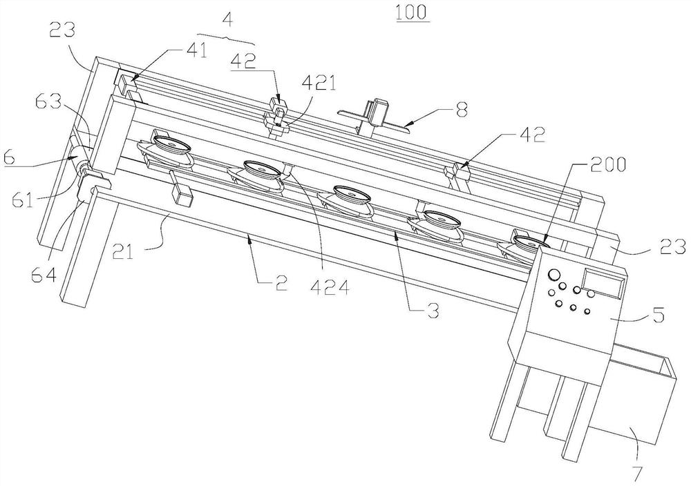
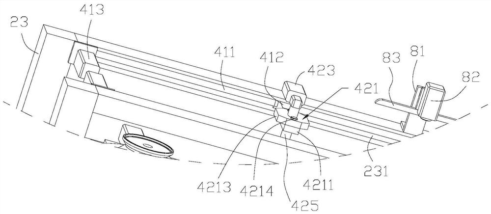
The invention provides a flash trimming machine, which includes a frame, a clamping mechanism, a controller and a flashing trimming device. The clamping mechanism is installed on the frame, and the clamping mechanism is evenly spaced along a first direction. Multiple clamping positions for clamping the workpiece; the trimming device includes a moving mechanism and a trimming mechanism, the moving mechanism is installed on the frame, and the trimming mechanism includes a mounting arm, a trimming tool and a rotating drive. The installation arm is connected with the moving mechanism, the edge trimming tool is installed on the installation arm, and the rotary drive part is connected with the edge trimming tool; the controller is connected with the rotary drive part and the moving mechanism, and is used to control the rotary drive part to drive the edge trimming tool to wrap around The outer periphery of the workpiece on the clamping position rotates by itself, and the moving mechanism is controlled to drive the flash trimming mechanism to move along the first direction, so as to perform flash trimming operations on multiple workpieces on the clamping mechanism. The flash trimming machine can improve the efficiency and quality of flash trimming. The invention also provides a method for trimming workpiece flash by using the flash trimmer.

Description

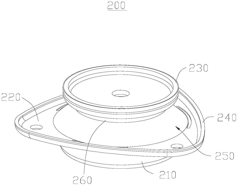
technical field [0001] The invention relates to flash trimming machine equipment, in particular to a flash trimming machine and a method for trimming workpiece flash by using the same. Background technique [0002] At present, the work of cutting the flash of the hub frame of the automobile stopper is manual operation, the work efficiency is extremely low, and the working environment is relatively harsh. It is difficult to ensure the uniformity of the cut flash by manual cutting of the flash. The quality of the car stopper hub frame shear flash. With the rapid development of the social economy and the change of the age structure of the population, labor costs continue to increase. Therefore, it is necessary to provide a flash trimming device that can reduce labor costs and improve work efficiency. Contents of the invention [0003] The invention aims to provide an edge trimmer capable of reducing labor costs and improving work efficiency. [0004] In order to achieve the...

Claims


Application Information

Patent Timeline
Patent Type & Authority Patents(China)
IPC IPC(8): B23D31/00B23D33/00B23D33/02
CPCB23D31/00B23D33/00B23D33/02
Inventor 潘宇倩彭永石杨灵敏吴相坤范才枝朱治均梁航覃祖业莫耀杰
Owner LUSHAN COLLEGE OF GUANGXI UNIV OF SCI & TECH
Learn More