

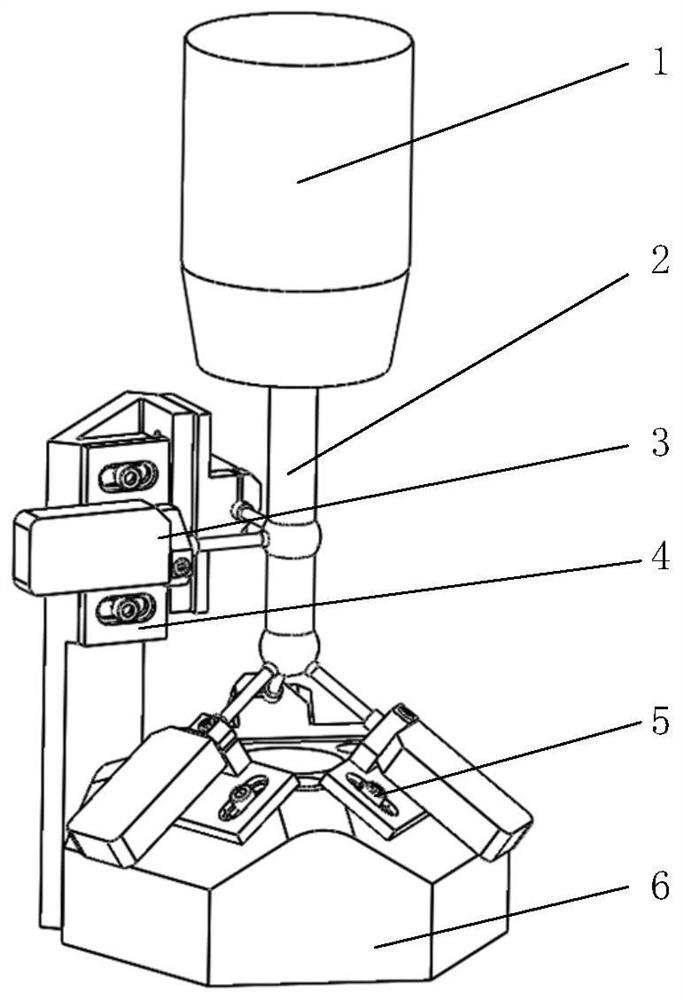
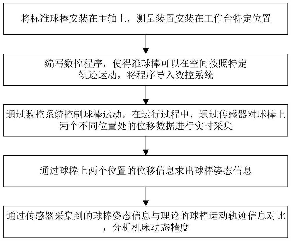
Device and method for detecting dynamic accuracy of CNC machine tools
A technology of dynamic accuracy and detection method, used in measuring/indicating equipment, metal processing mechanical parts, metal processing equipment, etc., can solve the problems of unable to detect tool axis error at the same time, unable to fully reflect the machine tool error, etc., to increase the accuracy and Reliability, improve measurement efficiency, and simplify the effect of the measurement process
- Summary
- Abstract
- Description
- Claims
- Application Information
AI Technical Summary
Problems solved by technology
Method used
Image

Examples
Embodiment Construction
[0037] The present invention will be described in detail below in conjunction with specific embodiments. The following examples will help those skilled in the art to further understand the present invention, but do not limit the present invention in any form. It should be noted that those skilled in the art can make several changes and improvements without departing from the concept of the present invention. These all belong to the protection scope of the present invention.
[0038] In the description of this application, it should be understood that the terms "upper", "lower", "front", "rear", "left", "right", "vertical", "horizontal", "top", The orientation or positional relationship indicated by "bottom", "inner", "outer", etc. is based on the orientation or positional relationship shown in the drawings, and is only for the convenience of describing the application and simplifying the description, rather than indicating or implying the referred device Or elements must hav...
PUM
 Abstract
Description
Claims
Application Information