
Lining-changing manipulator bridge structure and working method

A bridge structure and manipulator technology, applied in manipulators, program-controlled manipulators, metal processing, etc., can solve the problems of energy loss, high cost, inconvenient height adjustment, etc., and achieve highly accurate control and reduce friction.

Inactive Publication Date: 2020-06-02
合肥市春华起重机械有限公司
View PDF13 Cites 2 Cited by
  • Summary
  • Abstract
  • Description
  • Claims
  • Application Information

AI Technical Summary

Problems solved by technology

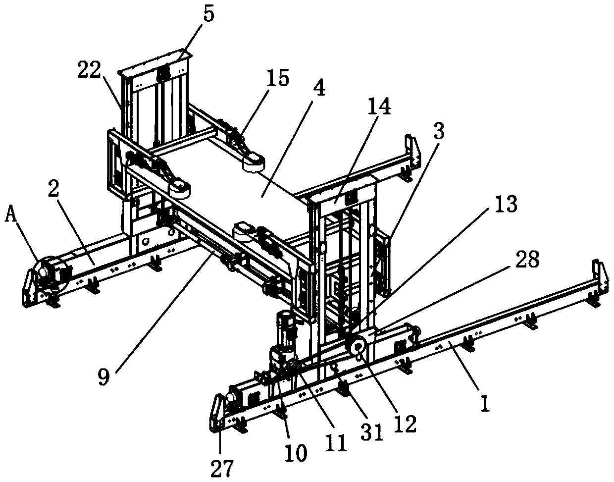
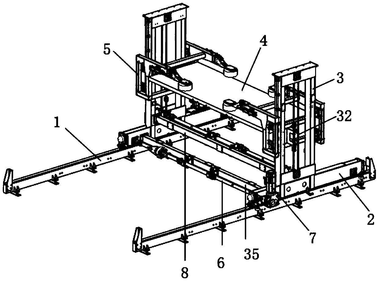
[0003] The purpose of the present invention is to provide a bridge structure and working method for a relining manipulator, by fixing with a second rotating shaft between two third transmission wheels, and by installing a second motor on the mobile base, the second motor The output shaft and the second rotating shaft are driven through the first transmission wheel, the second transmission wheel, and the first belt. The lifting bracket is installed vertically on the support column and fixed with the first belt. Between the two lifting brackets The vertical storage plate in between is used to place the liner, and the second motor can drive the lifting bracket to move in the vertical direction, thereby driving the storage plate to rise and fall, which solves the problem that the height of the bridge structure of the traditional lining manipulator is not easy to adjust. It is easy to cause energy loss and high cost technical problems when feeding materials;

Method used


Image

  • Lining-changing manipulator bridge structure and working method
  • Lining-changing manipulator bridge structure and working method
  • Lining-changing manipulator bridge structure and working method

Examples


Embodiment Construction

[0032] The technical solutions of the present invention will be clearly and completely described below in conjunction with the embodiments. Apparently, the described embodiments are only some of the embodiments of the present invention, not all of them. Based on the embodiments of the present invention, all other embodiments obtained by persons of ordinary skill in the art without creative efforts fall within the protection scope of the present invention.

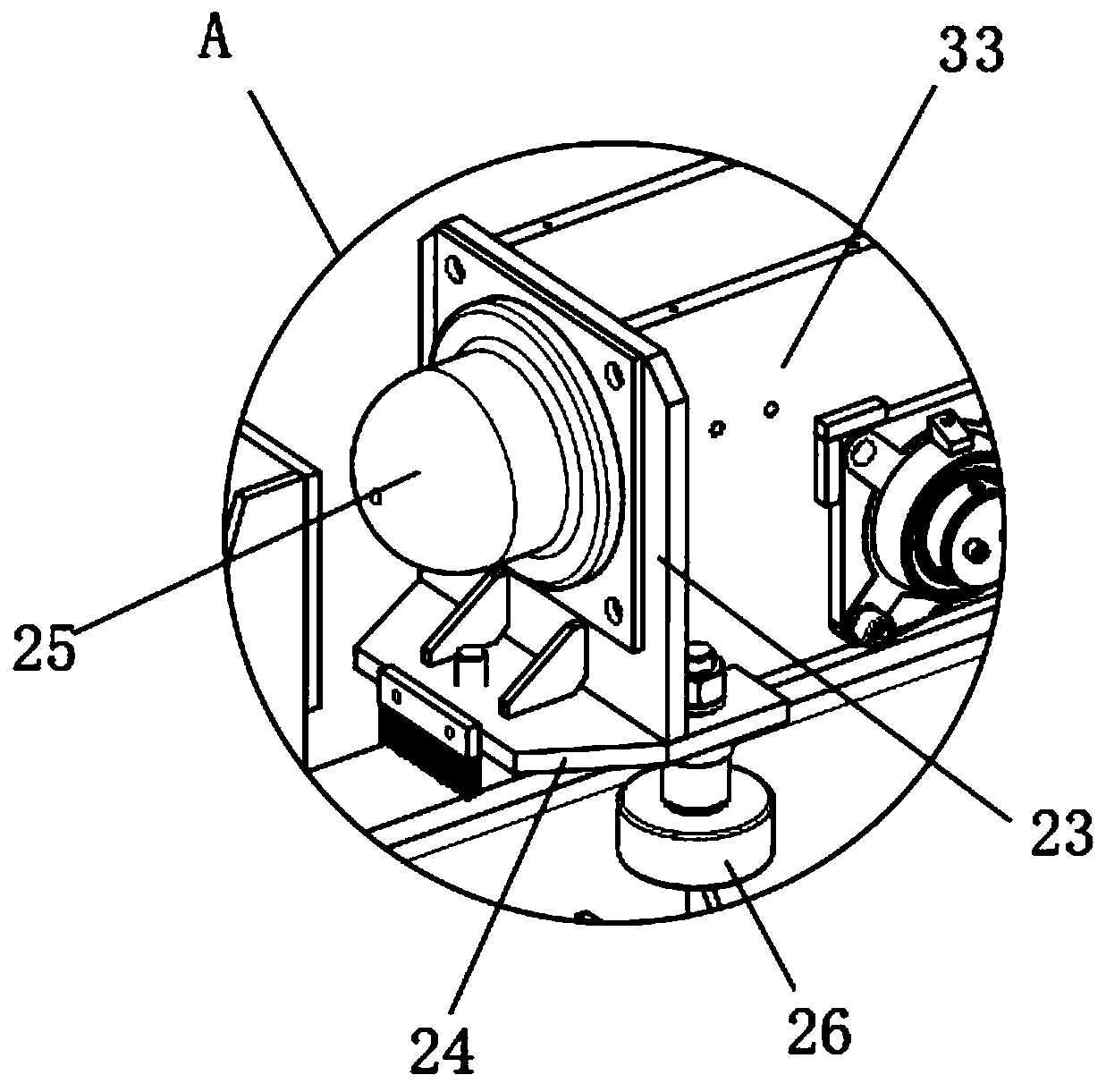
[0033] Such as Figure 1-6 As shown, a bridge structure of a relining manipulator includes two crossbeams 1, the two crossbeams 1 are parallel to each other, and a mobile base 2 is movably installed on the two crossbeams 1 along the horizontal direction. Two support columns 3 are provided, the bottom of the support column 3 is fixed to the mobile base 2 by welding, the upper surface of the mobile base 2 is fixedly installed with a second motor 10, and the output shaft end of the second motor 10 is fixed The first transmiss...


PUM


Abstract

The invention discloses a lining-changing manipulator bridge structure and a working method. The bridge structure comprises two cross beams, wherein movable bases are movably mounted on the two crossbeams in the horizontal direction; two supporting columns are vertically arranged on each movable base; a lifting bracket is movably mounted on each supporting column; each lifting bracket comprises two side frames; a cross rod is fixedly mounted at the top of each side frame; a swing arm is hinged to one end of each cross rod; a clamping wheel is mounted at the bottom of one end of each swing arm; a driving cylinder is hinged to the outer side of each cross rod; a connecting plate is hinged to the end part of an output rod of each driving cylinder; and one end of each connecting plate is fixedly connected with the corresponding swing arm through a bolt. The bridge structure is controllable in height, avoids energy loss, effectively saves the cost, facilitates clamping or loosening of a lining plate on a storage plate, can guarantee safety and stability of the lining plate in the transportation process, facilitates quick replacement of the mill lining plate, and avoids transportation instability caused by vibration of the lining plate.

Description

technical field [0001] The invention relates to a bridge structure, in particular to a bridge structure and a working method of a relining manipulator. Background technique [0002] The patent document (CN109822310A) discloses a bridge structure of a relining manipulator. The hand bridge structure uses a relining trolley to move and transport the liner, and the relining trolley cannot ensure the stability of the liner during transportation, so it is difficult to ensure the liner. safety, the height of the relining trolley in the bridge structure is fixed, and cannot be lifted. When placing the liner on the relining trolley, the liner needs to be transported to the height of the liner by equipment, which results in large energy loss and high cost. When the lining trolley moves to the edge, it is easy to collide and cause vibration, which makes the lining unstable. Contents of the invention [0003] The purpose of the present invention is to provide a bridge structure and w...

Claims


Application Information

Patent Timeline
IPC IPC(8): B25J9/00B25J9/10B25J15/00B23P19/00
CPCB23P19/00B25J9/0009B25J9/10B25J15/00
Inventor 王亚梅赵春梅
Owner 合肥市春华起重机械有限公司
Learn More