Conveying device, rubberizing device and conveying method

A technology of feeding device and driving device, which is applied in the directions of sending objects, thin material handling, transportation and packaging, etc., can solve the problems of uncontrollable unloading tension, easy breakage of the material belt, complicated structure, etc. feeding and ensuring the effect of feeding tension

Inactive Publication Date: 2020-06-02
GUANGDONG LYRIC ROBOT INTELLIGENT AUTOMATION CO LTD
View PDF18 Cites 1 Cited by
  • Summary
  • Abstract
  • Description
  • Claims
  • Application Information

AI Technical Summary

Problems solved by technology

However, the operating mechanism (such as the glue application mechanism) needs to move or rotate synchronously with the material belt during continuous and uniform feeding, otherwise the operation (such as material peeling or tape sticking) is prone to failure, so the structure is complicated
When feeding intermittently, the feeding device needs to feed according to the preset time interval. The existing feeding device generally uses a switch controller to switch and control the discharging mechanism of the feeding device, and controls the discharging mechanism to intermittently feed through the output switch control signal, so that the discharging mechanism Frequent stops are required, the feeding tension is not easy to control, and the material belt is easy to break

Method used


Image

  • Conveying device, rubberizing device and conveying method
  • Conveying device, rubberizing device and conveying method
  • Conveying device, rubberizing device and conveying method

Examples


Embodiment 1

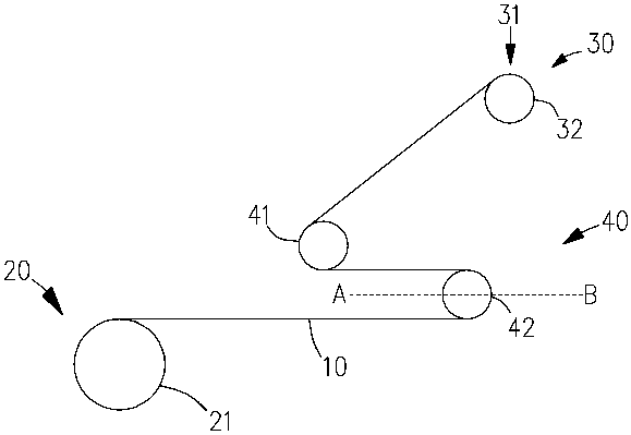
[0028] Please refer to figure 1 , in the first embodiment, the feeding device of the present invention mainly includes a discharge mechanism 20 for providing the material tape 10 provided on a frame not shown in the figure, and is used for carrying out the material tape 10 at the first preset position 31. An operating mechanism 30 for operations (such as but not limited to cutting, attaching materials, sucking materials, etc.), and a conveying mechanism 40 for transferring the material tape 10 from the discharging mechanism 20 to the first preset position 31 .

[0029] In this embodiment, the unwinding mechanism 20 includes an unwinding wheel 21 driven by the driving mechanism, and the strip 10 is long and wound on the unwinding wheel 21 . Driven by the drive mechanism, the unwinding wheel 21 rotates at a constant speed for unwinding.

[0030] The conveying mechanism 40 includes a temporary storage mechanism for temporarily storing at least a part of the material tape release...

Embodiment 2

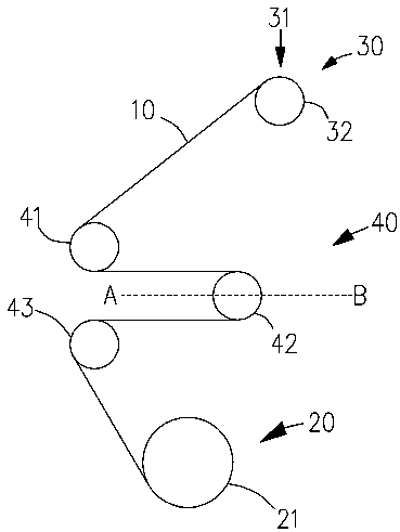
[0036] Please refer to figure 2 The main difference between the second embodiment and the first embodiment is that there is a third transmission member 43 between the second transmission member 42 and the discharge mechanism 20 . The third transmission member 43 is similar in structure to the first transmission member 41, and is a rotatable wheel or shaft, on which is formed a slot for position limitation, and the material strip 10 is located in the slot. The second transmission member 42 moves between two end points A (second preset position) and end point B (third preset position) of the dotted line segment AB. The end point A, that is, the second preset position is close to the first transmission member 41 and the third transmission member 43 , and the end point B, that is, the third preset position is away from the first transmission member 41 and the third transmission member 43 . The third transmission member 43 is disposed at the same distance from the end point A and...

Embodiment 3

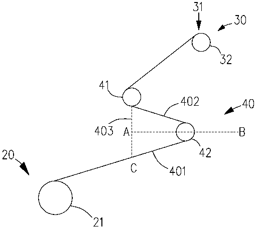
[0041] Please refer to image 3 The main difference between the third embodiment and the first embodiment is that the material belt 10 between the first transmission member 41 and the second transmission member 42 is not parallel to the material belt between the second transmission member 42 and the discharge mechanism 20 . The first transmission member 41 as the output end of the temporary storage mechanism is located on the side of the end point A of the dotted line segment BA (the intersection point of the perpendicular line from the central axis of the first transmission member 41 to the line segment AB and the straight line AB is the end point A), as the input end The unwinding wheel 21 is located on one side of the extended line of the dotted line segment BA. In this way, the output speed of the temporary storage mechanism when the second transmission member 42 moves between AB can be calculated according to the plane geometric relationship between the first transmission...


PUM


Abstract

The invention relates to a conveying device. The conveying device comprises a discharging mechanism and a conveying mechanism for conveying a material strip to a first preset position from the discharging mechanism. The conveying mechanism comprises a temporary storage mechanism for temporarily storing at least one part of the material strip discharged by the discharging mechanism every other preset time. According to the conveying device, the temporary storage mechanism is arranged, so that the material strip located at the first preset position is static, or the moving speed is reduced, andthe success rate of operation of an operation mechanism on the material strip is increased. Meanwhile, the discharging mechanism is allowed to carrying out discharging continuously, and stable discharging tension is ensured.

Description

technical field [0001] The invention relates to the field of automatic production, in particular to a feeding device, a gluing device and a feeding method. Background technique [0002] In the field of automated production, feeding devices are usually used to automatically provide materials to other equipment for processing. Among them, the feeding device for conveying the strip-shaped base tape loaded with materials has two modes of continuous and uniform feeding and intermittent feeding. When feeding continuously and evenly, the feeding device only needs to work continuously and stably. However, the operating mechanism (such as the glue application mechanism) needs to move or rotate synchronously with the material belt during continuous and uniform feeding, otherwise the operation (such as material peeling or tape sticking) is likely to fail, so the structure is complicated. When feeding intermittently, the feeding device needs to feed according to the preset time interv...

Claims


Application Information

Patent Timeline
Patent Type & Authority Applications(China)
IPC IPC(8): B65H20/34B65H37/04B65H16/10B65H23/26B65H18/10
CPCB65H16/10B65H18/10B65H20/34B65H23/26B65H37/04B65H2515/31
Inventor 黄振奎丘荣意杨太列周俊杰杜义贤
Owner GUANGDONG LYRIC ROBOT INTELLIGENT AUTOMATION CO LTD
Why Eureka
Try Eureka