
Combined type section steel support rod piece

A support rod and combined technology, used in excavation, construction, infrastructure engineering, etc., can solve the problems of difficulty in ensuring welding quality in foundation pit engineering, the gap between the load capacity of strong shaft and weak bearing, and the inability of material strength to fully exert. The effect of reducing the risk of foundation pit use, long turnaround period, and reducing the impact of human and weather factors

Pending Publication Date: 2020-06-02
BEIJING ZHONGYAN DADI TECH CO LTD
View PDF0 Cites 3 Cited by
  • Summary
  • Abstract
  • Description
  • Claims
  • Application Information

AI Technical Summary

Problems solved by technology

However, the current steel support rods are generally round steel pipes or HW-type H-shaped steel. The installation of round steel pipes requires a lot of welding work. It is difficult to ensure the welding quality in the working environment of foundation pit engineering, which not only affects the construction progress, but also has certain problems. Security risks
As for the H-shaped steel of the HW type, there is an obvious gap between the strong shaft and the weak shaft in the bearing capacity, and the material strength cannot be fully exerted, resulting in economic waste.

Method used


Image

  • Combined type section steel support rod piece
  • Combined type section steel support rod piece
  • Combined type section steel support rod piece

Examples


Embodiment Construction

[0035] In order to make the technical problems, technical solutions and beneficial effects to be solved by the present invention clearer and clearer, the present invention will be further described in detail below in conjunction with the accompanying drawings and embodiments. The specific embodiments described here are only used to explain the present invention, not to limit the present invention.

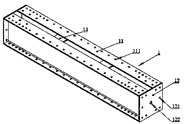
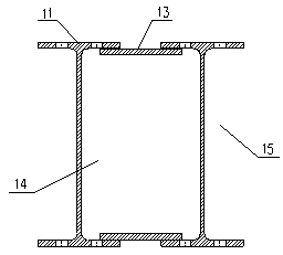
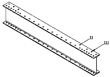
[0036] Such as figure 1 As shown, the combined section steel support bar 1 includes section steel 11 , end plate 12 and trim plate 13 . Such as figure 2 As shown, a pair of profiled steels 11 spliced ​​into a combined profiled steel support bar 1 has a rectangular space 14 formed in its cross section and grooved spaces 15 on both sides. Such as image 3 As shown, the shaped steel 11 is an H-shaped steel, and bolt holes 111 are reserved in the flange plate. The end portion of the combined shaped steel support bar 1 is welded with an end plate 12, and the end plate 12 can comple...


PUM

PropertyMeasurementUnit
Lengthaaaaaaaaaa

Abstract

The invention relates to a combined type section steel support rod piece which adopts a pair of H section steel connected through a batten plate to form an integrity; the combined type section steel support rod piece is mainly used for horizontal support of a foundation pit; to facilitate transportation and installation, the combined type section steel support rod piece is manufactured by adoptingthe length of certain modulus; end plates are welded to the two ends of each support rod piece, and bolt holes are reserved in the two ends of the support rod piece; at the same time, the bolt holesare also reserved at certain intervals in a section steel flange plate; the support rod pieces are spliced through the end plates and the bolt holes reserved in the flange plate to realize steel structure prefabricated construction; the support rod piece is machined into a standard component in a factory, then, the standard component is transported to a building construction site, and onsite assembling and installation are realized through bolt connection, so that the construction efficiency of a foundation pit horizontal support structure can be greatly improved; and after the using period ofthe foundation pit horizontal support structure is finished, the support rod piece is dismantled and maintained for next engineering, so that environmentally-friendly construction is realized, and the construction cost is effectively reduced.

Description

technical field [0001] The invention relates to an assembled horizontal support structure for foundation pit engineering, in particular to a combined section steel support bar composed of H section steel. Background technique [0002] With the large-scale development and application of prefabricated structures in my country, the prefabricated technology is becoming more and more mature. As a temporary project, the foundation pit does not need to consider more about durability and complex loads, and the prefabricated type will definitely become the development trend of foundation pit engineering. At present, the horizontal support of foundation pit engineering is still dominated by anchor rods and reinforced concrete supports. The anchor rods are generally anchored outside the foundation pit, which will affect the development of adjacent plots. A large amount of construction waste will be formed, and the city will face greater pressure on environmental protection. [0003] ...

Claims


Application Information

Patent Timeline
IPC IPC(8): E02D17/04
CPCE02D17/04
Inventor 张兴刘光磊武思宇童希明
Owner BEIJING ZHONGYAN DADI TECH CO LTD
Learn More