
Vibration reduction assembly with upward vibration constraint structure as well as air conditioner

A technology of vibration-damping components and vibration-damping pads, which is applied in the direction of pump components, variable-capacity pump components, machines/engines, etc., can solve problems such as poor vibration-damping effects, achieve high transportation reliability, avoid repeated friction damage, reduce The effect of amplitude

Pending Publication Date: 2020-06-02
GREE ELECTRIC APPLIANCES INC
View PDF8 Cites 0 Cited by
  • Summary
  • Abstract
  • Description
  • Claims
  • Application Information

AI Technical Summary

Problems solved by technology

[0006] An embodiment of the present invention provides a vibration damping assembly and an air conditioner with an upward vibration restraint structure to solve the problem that there is no effective vibration limiting structure on the top surface of the vibration damping pad in the prior art, and the vibration damping effect is poor

Method used


Image

  • Vibration reduction assembly with upward vibration constraint structure as well as air conditioner
  • Vibration reduction assembly with upward vibration constraint structure as well as air conditioner
  • Vibration reduction assembly with upward vibration constraint structure as well as air conditioner

Examples


Embodiment Construction

[0026] The present invention will be further described in detail below with reference to the drawings and specific embodiments, but it is not intended to limit the present invention.

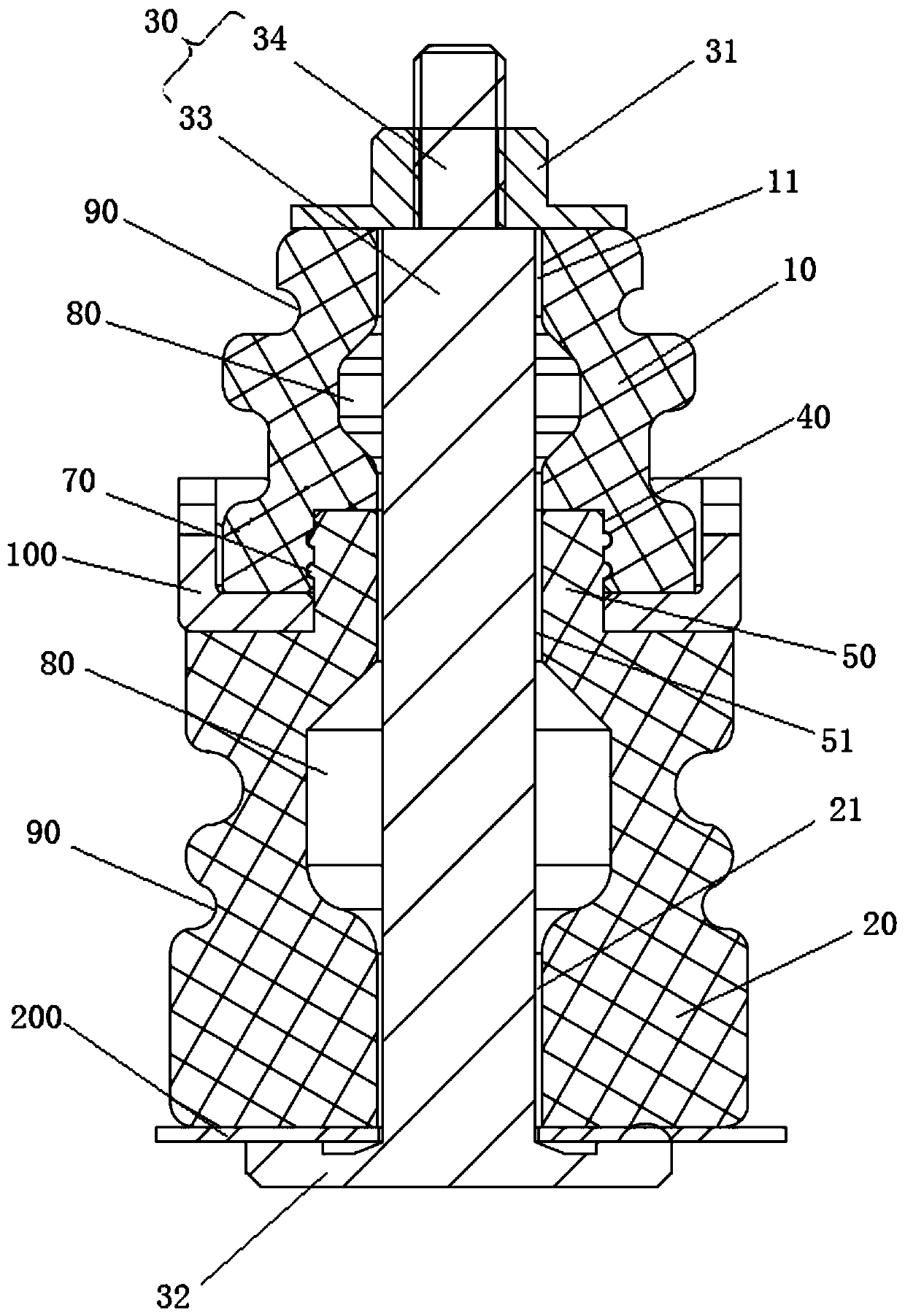
[0027] Such as Figure 3 to Figure 5 As shown, the vibration damping assembly with the upward vibration restraint structure of the first embodiment is used to mount the mounting plate 100 of the compressor on the chassis 200, thereby damping the compressor. The damping assembly includes an upper damping pad 10, a lower damping pad 20 and a positioning rod 30. Wherein, the lower end surface of the upper damping pad 10 and the upper end surface of the lower damping pad 20 jointly clamp the mounting plate 100 of the compressor. The upper damping pad 10 has a first through hole 11 penetrating in the axial direction, and the lower damping pad 20 has a second through hole 21 penetrating in the axial direction. The first through hole 11 corresponds to the second through hole 21. The positioning rod 30 p...


PUM


Abstract

The invention discloses a vibration reduction assembly with an upward vibration constraint structure as well as an air conditioner. The vibration reduction assembly comprises an upper vibration reduction pad, a lower vibration reduction pad and a limiting rod, wherein the lower end face of the upper vibration reduction pad and the upper end face of the lower vibration reduction pad jointly clamp amounting plate of a component to be subjected to vibration reduction, a first through hole penetrating in the axial direction is formed in the upper vibration reduction pad, a second through hole penetrating in the axial direction is formed in the lower vibration reduction pad, and the first through hole corresponds to the second through hole; and the positioning rod is arranged in the first through hole and the second through hole in a penetrating mode, wherein a first limiting structure is arranged at the upper end of the positioning rod, a second limiting structure is arranged at the lowerend of the positioning rod, at least one of the first limiting structure and the second limiting structure is detachably connected with the positioning rod, and the first limiting structure is in close fit with the upper end face of the upper vibration reduction pad. According to the technical scheme, the problem that in the prior art, vibration reduction effects are poor due to the fact that thetop faces of the vibration reduction pads are not provided with the structures for effectively limiting vibration can be solved.

Description

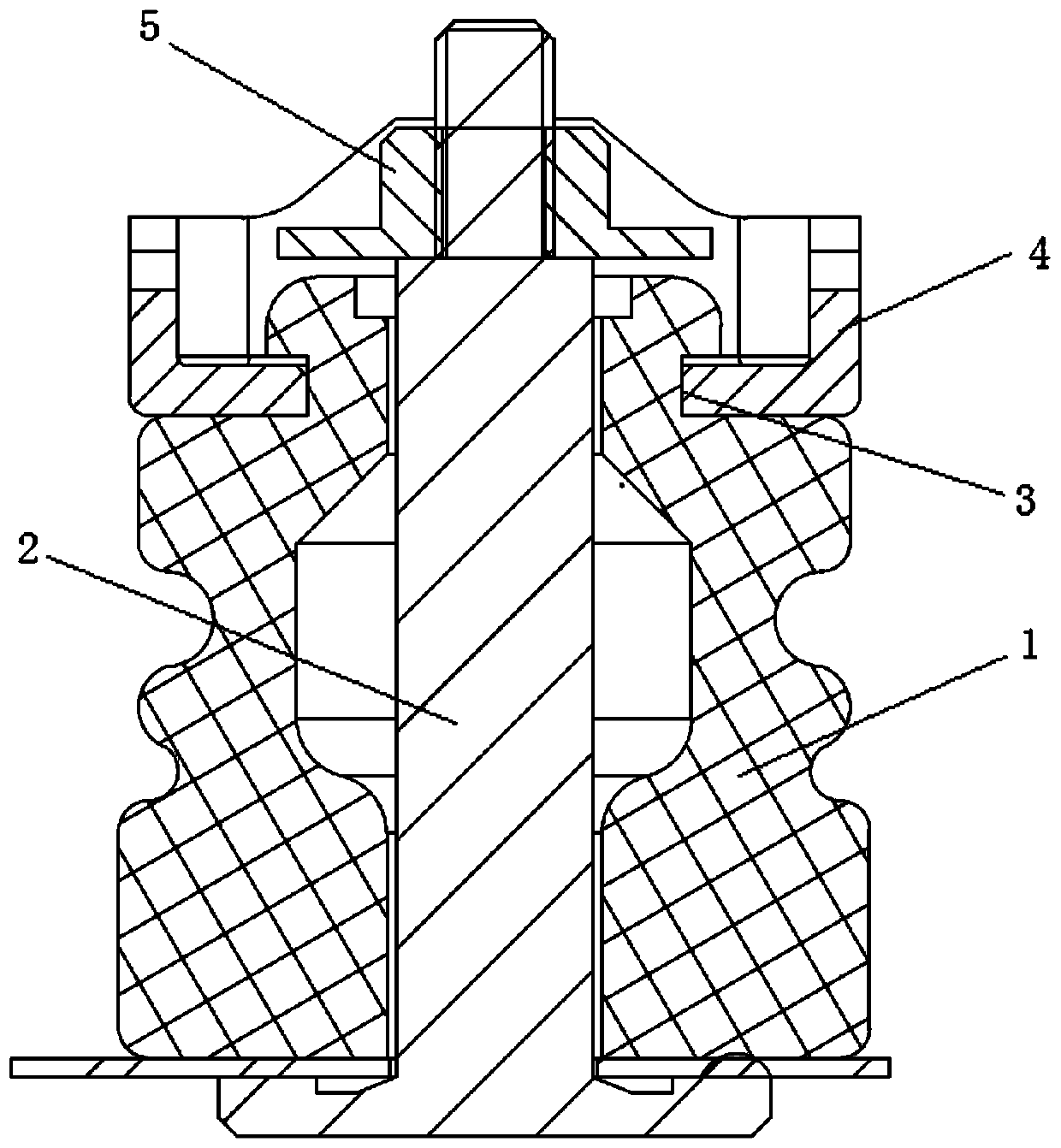
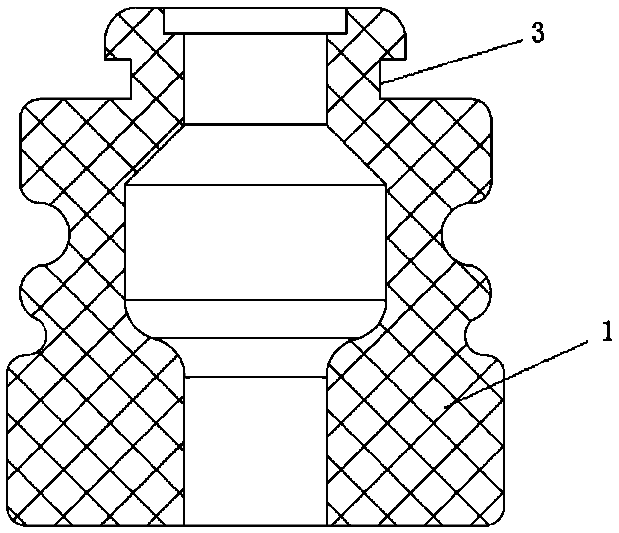
Technical field [0001] The present invention relates to the technical field of refrigeration, and in particular to a vibration damping assembly and an air conditioner with an upward vibration restraint structure. Background technique [0002] At present, the feet of air conditioner compressors are generally installed on the chassis through damping pads. The damping pads support the compressor, reduce vibration and noise, and protect copper pipes during transportation, long-term operation, and frequent switching of fixed-frequency external machines. The impact of the reliability of the time. [0003] Such as figure 1 with figure 2 As shown, the existing vibration damping pad 1 is an integral structure with a through hole in the middle, and the bottom of the positioning bolt 2 is spot welded to the outer chassis. The positioning bolt 2 passes upward through the through hole of the vibration damping pad 1 to reduce The top of the vibration pad 1 has an annular mounting groove 3, and...

Claims


Application Information

Patent Timeline
Patent Type & Authority Applications(China)
IPC IPC(8): F04B39/00
CPCF04B39/0044
Inventor 魏书生
Owner GREE ELECTRIC APPLIANCES INC
Learn More