
Resistor

A technology of resistors and resistor strips, applied in the direction of fixed resistor devices for taps, etc., can solve problems such as noise interference, inapplicability, and low voltage resolution

Active Publication Date: 2022-07-19
致茂电子(苏州)有限公司
View PDF8 Cites 0 Cited by
  • Summary
  • Abstract
  • Description
  • Claims
  • Application Information

AI Technical Summary

Problems solved by technology

However, the traditional voltage division method is susceptible to noise interference, and the voltage resolution is low, so it is often impossible to fine-tune the appropriate voltage signal
In addition, the traditional voltage division method often uses large-area resistors or complex electronic components, because the circuit size is getting smaller and smaller, the traditional voltage division method is becoming more and more unsuitable

Method used


Image

  • Resistor
  • Resistor
  • Resistor

Examples


Embodiment Construction

[0028] The foregoing and other technical contents, features and effects of the present invention will be clearly presented in the following detailed description of a preferred embodiment with reference to the accompanying drawings. The directional terms mentioned in the following embodiments, such as: up, down, left, right, front or rear, etc., are only referring to the directions of the drawings. Accordingly, the directional terms used are illustrative and not limiting of the present invention.

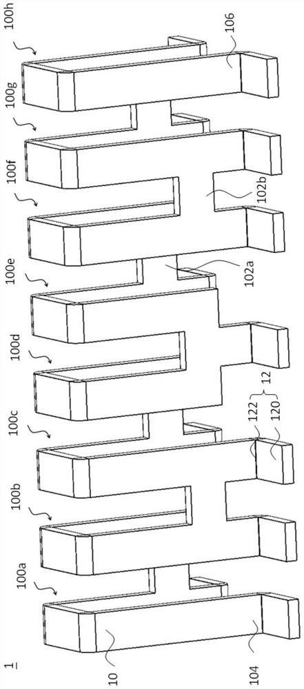
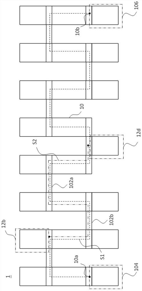
[0029] Please also refer to figure 1 and figure 2 , figure 1 is a three-dimensional schematic diagram illustrating a resistor according to an embodiment of the present invention, figure 2 It is a schematic top view of a resistor according to an embodiment of the present invention. As shown in the figure, the resistor 1 includes a resistance bar 10 and a plurality of shunt connection parts 12, the resistance bar 10 and the plurality of shunt connection parts 12 are both made of ...


PUM


Abstract

The invention provides a resistor, which includes a resistance bar and a plurality of shunt connection parts. The resistance bar has a first end and a second end, the resistance bar provides a first current path, and the first current path extends along the resistance bar from the first end to the second end. The plurality of shunt connection parts are electrically connected to different positions of the first current path, and each shunt connection part has a pin. Wherein, the distance between the first end and the second end is smaller than the length of the first current path, and the resistance strip and the pins of the plurality of shunt connection parts are not coplanar. The first end and the second end are used to electrically connect to a power source, two of the plurality of shunt connection parts are selected, and a shunt voltage is obtained from the selected two shunt connection parts.

Description

technical field [0001] The present invention relates to a resistor, in particular to a resistor with multiple pins, and different resistance values ​​can be obtained by selecting different pins. Background technique [0002] Since the specifications of different types of electronic devices may be different, engineers need to adjust the settings of the testing equipment when testing these different types of electronic devices, so as to correctly test these electronic devices. For example, the voltage signal output by the detection device needs to fall within a preset range so that the electronic device can correctly interpret it. In practice, it is common to step down the larger voltage from the voltage source by means of voltage division, so as to fine-tune the appropriate voltage signal. However, the traditional voltage dividing method is susceptible to noise interference, and the voltage resolution is low, so it is often impossible to fine-tune a suitable voltage signal. ...

Claims


Application Information

Patent Timeline
Patent Type & Authority Patents(China)
IPC IPC(8): H01C10/46
CPCH01C10/46
Inventor 刘崇琳黄建兴陈文钟
Owner 致茂电子(苏州)有限公司
Learn More