Chip mounting equipment based on mobile phone camera chip

A mobile phone camera and chip technology, applied in the manufacture of conveyor objects, electrical components, semiconductor/solid-state devices, etc., can solve the problems of secondary pollution of products, product pollution, and single production model.

Pending Publication Date: 2020-06-02
苏州美仪自动化设备有限公司
View PDF0 Cites 5 Cited by
  • Summary
  • Abstract
  • Description
  • Claims
  • Application Information

AI Technical Summary

Problems solved by technology

This process needs to manually attach each camera module to the steel sheet carrier tape, and then put them into the finished product storage box; however, manual work is not only inefficient, but also labor-intensive, and it is more likely to cause secondary damage to the product. Pollution, cable breakage, etc., have a great impact on product quality
The existing other similar equipment has a single production model, low efficiency, occupying labor costs, and causing different degrees of pollution to the product

Method used


Image

  • Chip mounting equipment based on mobile phone camera chip
  • Chip mounting equipment based on mobile phone camera chip
  • Chip mounting equipment based on mobile phone camera chip

Examples


Embodiment

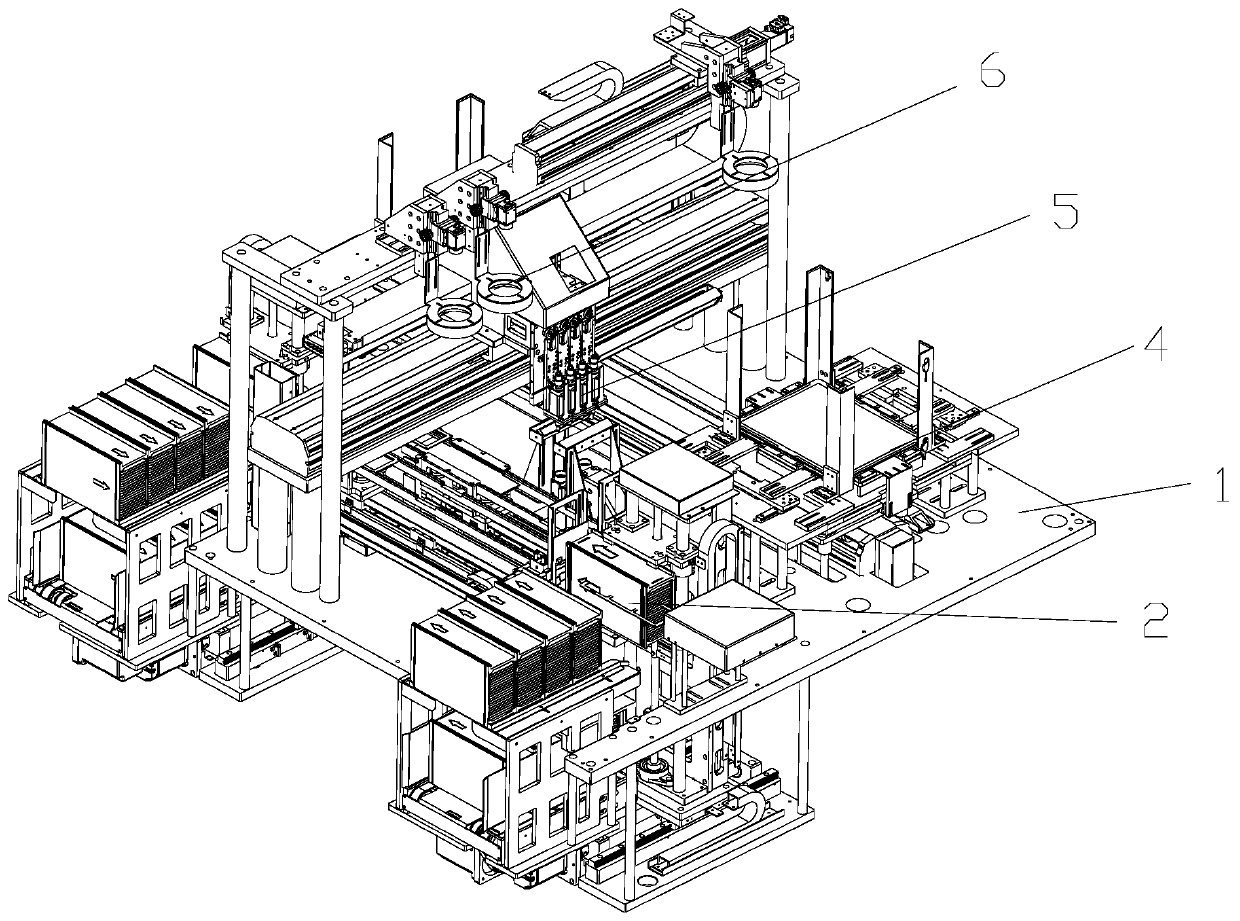
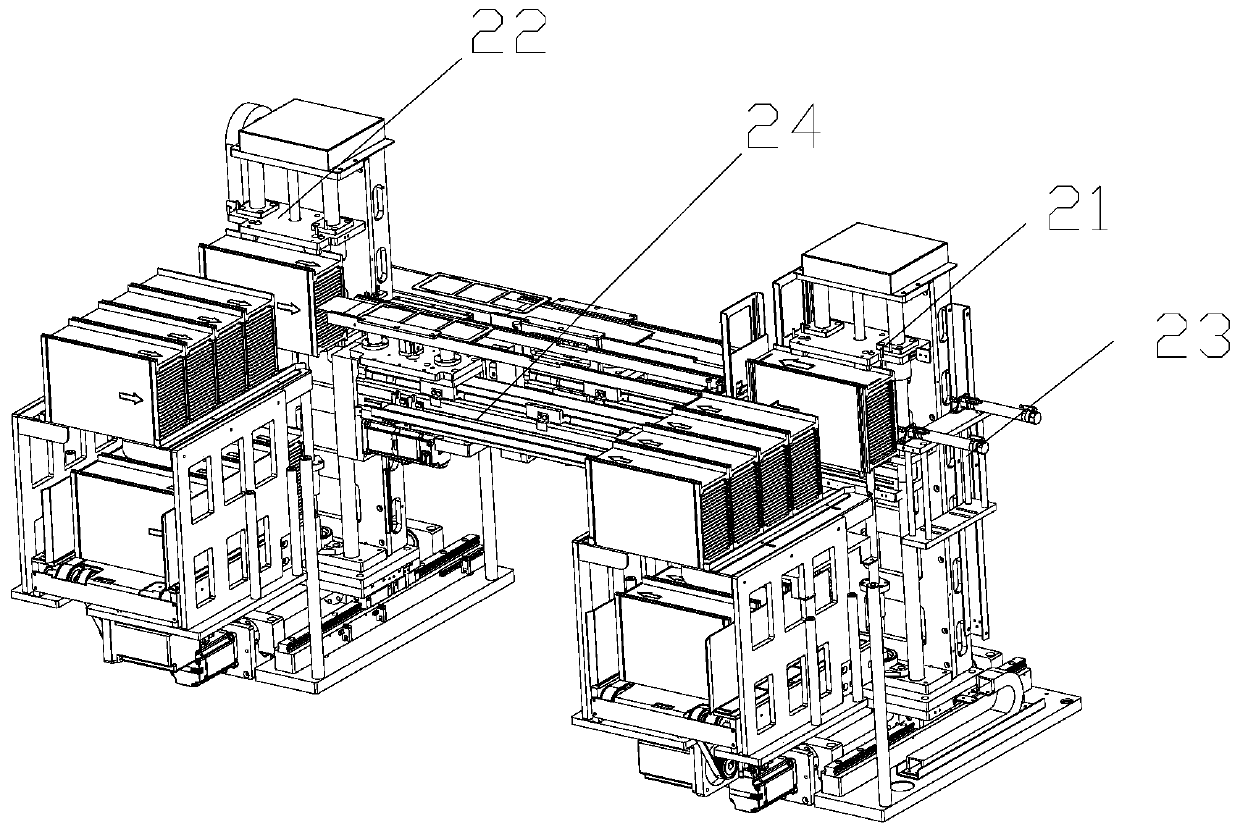
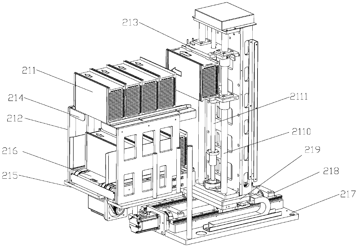
[0031] Example: such as figure 1 ~ Figure 7Shown, a kind of chip mounting equipment based on the mobile phone camera includes a work platform 1, and the work platform 1 is provided with a steel sheet carrying tape receiving and discharging cycle mechanism 2, a chip product handling mechanism 3, a chip product feeding mechanism 4 and Camera positioning detection mechanism 5; the steel sheet carrier tape receiving and discharging cycle mechanism 2 includes a steel sheet carrier tape discharging device 21, a steel sheet carrier tape receiving device 22, a steel sheet carrier tape pushing device 23 and a steel sheet carrier tape feeding device 23. Belt conveying device 24; the steel sheet carrying tape discharging device 21 is identical in structure to the steel sheet carrying tape receiving device 22 and is arranged correspondingly front and back, both including several magazine magazines 211, storage brackets 212 and movable jaws 213; the magazine magazine 211 is provided wit...

Embodiment approach

[0035] The biaxial transmission device includes a bottom plate 217, on which a second ball screw motor module 218 is arranged, and the screw nut on the second ball screw motor module 218 is fixedly connected to the moving support plate 219 and Carry the moving support plate 219 to do left and right linear reciprocating motions; the moving support plate 219 is provided with two left and right corresponding and vertically placed optical axes 2110 and a third ball screw motor module 2111, the movable The clamping jaw 213 is arranged on the optical axis 2110, and at the same time, the lead screw nut of the third ball screw motor module 2111 is fixedly connected to the movable clamping jaw 213 and carries the movable clamping jaw 213 to reciprocate in a straight line up and down. Movement; the working principle of the steel sheet loading and unloading cycle mechanism 2 is: the movable jaw 213 is connected to the biaxial transmission device, and the movable jaw 213 can be freely move...


PUM


Abstract

The invention discloses chip mounting equipment based on a mobile phone camera chip, which comprises a steel sheet carrier tape receiving and discharging circulating mechanism, a chip product carryingmechanism, a chip product feeding mechanism and a camera positioning detection mechanism, wherein the steel sheet carrier tape receiving and discharging circulating mechanism comprises a steel sheetcarrier tape discharging device, a steel sheet carrier tape receiving device, a steel sheet carrier tape pushing device and a steel sheet carrier tape conveying device; the chip product carrying mechanism comprises a suction device and a moving device; and the chip product feeding mechanism comprises a Tray, two Tray stacking devices which are correspondingly arranged front and back, and a Tray transfer device. The equipment is used for carrying out steel sheet carrier tape packaging on the mobile phone camera chip, a mobile phone camera chip product is placed on an insulating carrier tape ofa steel sheet and is protected through the insulating carrier tape, the whole equipment runs in a full-automatic mode, the packaging precision is high, and the working efficiency can be greatly improved.

Description

technical field [0001] The invention belongs to the technical field of automation equipment, and in particular relates to a chip placement equipment based on a camera of a mobile phone. Background technique [0002] Mobile phone cameras usually use a motor with a metal shell. Since the iron shell is an electrical conductor, after installing the motor with a metal iron shell on the main board of the mobile phone, it is easy to touch the electronic components on the main board, causing the electronic components on the main board to be damaged. The device is short-circuited, resulting in defective products of the mobile phone camera. In order to solve the above problems, insulating tape is usually used to wrap the insulating paper around the iron shell of the motor, which plays an insulating role, prevents the iron shell from touching the electronic components on the motherboard, and prevents short circuits between electronic components. . During the production process of the...

Claims


Application Information

Patent Timeline
IPC IPC(8): H01L21/67H01L21/677
CPCH01L21/67121H01L21/67259H01L21/67265H01L21/67766
Inventor 李海新黄凤先邱明超
Owner 苏州美仪自动化设备有限公司
Why Eureka
Try Eureka