Online centralized detection and management device utilizing OTDR

A management equipment and centralized technology, applied in the field of OTDR, can solve the problems of unstable current signal frequency, easy loosening at the connection port, and not supporting temperature detection, so as to ensure the tightness, improve the detection items, and prevent the optical fiber from overheating. high effect

Active Publication Date: 2020-06-02
WUXI KEY SENSOR PHOTONICS TECH
View PDF25 Cites 2 Cited by
  • Summary
  • Abstract
  • Description
  • Claims
  • Application Information

AI Technical Summary

Problems solved by technology

[0002] The existing online centralized detection and management equipment using OTDR, because the equipment needs to switch and detect multiple optical fibers in daily use, after a long period of use of the equipment, it is connected to the optical fiber. When the optical fiber is tested, the connection port is easy The situation of looseness causes the frequency of the current signal to be unstable, which affects the detection effect. Secondly, the surface of the optical fiber will generate high temperature when it is used, and most of the existing equipment does not support temperature detection. Although other data of the optical fiber are detected, the temperature data cannot be detected. It is judged that there are still potential safety hazards. Therefore, we propose to ensure the fastness of the connection between the optical fiber and the optical fiber interface, to avoid the loosening of the connection between the optical fiber and the optical fiber interface, resulting in unstable frequency of the current signal, to realize the work of temperature detection, and to further improve the detection items. To prevent the occurrence of fire accidents due to excessive temperature of the optical fiber, to solve the above problems

Method used


Image

  • Online centralized detection and management device utilizing OTDR
  • Online centralized detection and management device utilizing OTDR
  • Online centralized detection and management device utilizing OTDR

Examples


Embodiment Construction

[0020] The specific implementation manner of the present invention will be described in detail below in conjunction with the accompanying drawings.

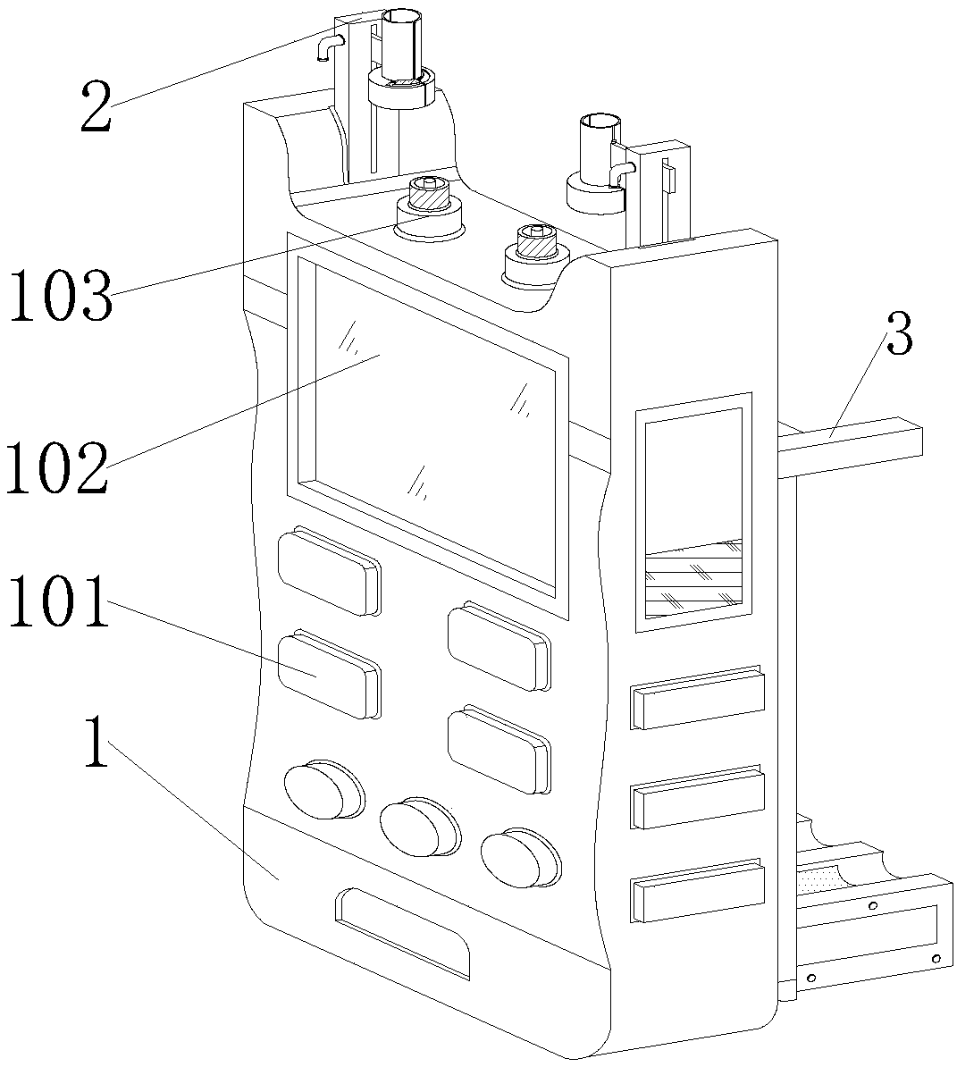
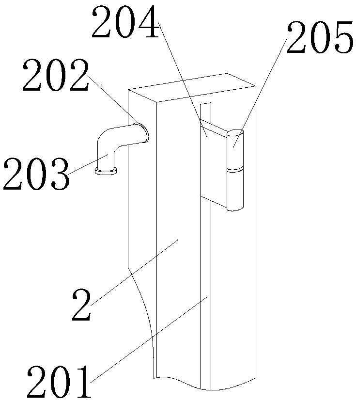
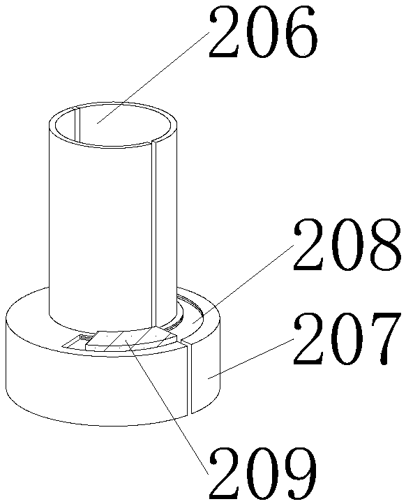
[0021] see Figure 1-5 As shown, an online centralized detection and management equipment using OTDR, the online centralized detection and management equipment using OTDR includes an optical time domain reflectometer 1 and a fixed plate 2, and the left and right sides of the top inner wall of the optical time domain reflectometer 1 are fixedly connected with fixed Board 2; the top of the optical time domain reflectometer 1 is electrically connected to the optical fiber interface 103 inside the fixed board 2, and the front end of the fixed board 2 has a movable groove 201, and the upper left side of the fixed board 2 has a small hole 202, and the small hole 202 and the movable groove 201 communicate with each other, the inside of the small hole 202 is rotatably connected with the card shaft 203, and the inside of the movable groov...


PUM


Abstract

The invention provides an on-line centralized detection and management device using an OTDR. The invention relates to the technical field of OTDR. An optical fiber interface is electrically connectedto the top end of the optical time domain reflectometer and located in a fixing plate; a movable groove is formed in a front end of the fixed plate; a small hole is formed above a left side of the fixed plate; the small holes are communicated with the movable groove; a clamping shaft is rotationally connected into the small hole; a movable plate is slidably connected into the movable groove; a front end of the movable plate is rotatably connected with a rotating shaft, a front end of the rotating shaft is rotatably connected with an opening and closing cylinder, a bottom end of the opening andclosing cylinder is fixedly connected with an interface cylinder, left and right sides of a rear end of the optical time domain reflectometer are fixedly connected with supporting strips, slideways are formed in the inner walls of the supporting strips, and an inner shaft is arranged between the slideways to ensure connection tightness. Temperature detection work is realized, detection items arefurther perfected, and the problem of unstable current signal frequency and fire accidents caused by over-high optical fiber temperature due to looseness of the connection port of the optical fiber and the optical fiber interface is solved.

Description

technical field [0001] The invention relates to the technical field of OTDR, in particular to an online centralized detection and management device utilizing OTDR. Background technique [0002] The existing online centralized detection and management equipment using OTDR, because the equipment needs to switch and detect multiple optical fibers in daily use, after a long period of use of the equipment, it is connected to the optical fiber, and the connection port is easy to detect when the optical fiber is detected. The situation of loosening causes the frequency of the current signal to be unstable, which affects the detection effect. Secondly, the surface of the optical fiber will generate high temperature when it is used, and most of the existing equipment does not support temperature detection. Although other data of the optical fiber are detected, the temperature data cannot be detected. It is judged that there are still potential safety hazards. Therefore, we propose to...

Claims


Application Information

Patent Timeline
Patent Type & Authority Applications(China)
IPC IPC(8): H04B10/071
CPCH04B10/071
Inventor 郭海涛施运强夏厦王一川
Owner WUXI KEY SENSOR PHOTONICS TECH
Why Eureka
Try Eureka