
Convex profile and application method thereof

A profile and connecting plate technology, applied in the installation of rack/frame structure, electrical components, support structure, etc., can solve the problems of complex assembly method, low degree of generalization of spare parts in the cabinet, unfavorable standardization, mass production, etc.

Pending Publication Date: 2020-06-02
戴鸿泽
View PDF0 Cites 0 Cited by
  • Summary
  • Abstract
  • Description
  • Claims
  • Application Information

AI Technical Summary

Problems solved by technology

The cabinet frame is a key component of an electrical equipment cabinet, and the key to assembling the cabinet frame is the connection between the three axially arranged profile parts at the corners x, y, and z of the frame; the background technology generally requires a large number of connecting accessories or Welding is used to realize the connection between three axially arranged profile parts. At present, there are problems: the assembly method is too complicated and requires a large number of special connection accessories or welding to realize the fast connection of the frame, and the use of the same The cabinets assembled from different profiles cannot meet the needs of different cabinet types, resulting in low universalization of spare parts in the cabinet, high manufacturing costs and low production efficiency, which is not conducive to standardization and mass production

Method used


Image

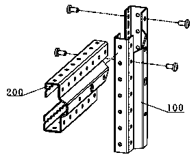
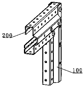
  • Convex profile and application method thereof
  • Convex profile and application method thereof
  • Convex profile and application method thereof

Examples


Embodiment 1

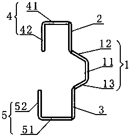
[0105] like figure 1 As shown, a convex profile includes a C-shaped connecting plate 1, an upper vertical plate 2, a lower vertical plate 3, an upper inverted L-shaped plate 4 and a lower L-shaped plate 5, and the C-shaped connecting plate 1 includes a bottom plate 11 and the upper connection plate 12 and the lower connection plate 13 connected to the two ends of the bottom plate 11;

[0106] The upper inverted L-shaped plate 4 is composed of a vertically connected upper horizontal plate 41 and an upper vertical plate 42, and the lower L-shaped plate 5 is composed of a vertically connected lower horizontal plate 51 and a lower vertical plate 52. The C-shaped connection The end of the upper connecting plate 12 of the plate 1 is connected to the lower end of the upper vertical plate 2, and the end of the lower connecting plate 13 is connected to the upper end of the lower vertical plate 3; the upper end of the upper vertical plate 2 is vertically connected to the upper horizont...

Embodiment 2

[0134] like Figure 11 As shown, a convex profile includes a C-shaped connecting plate 1, an upper vertical plate 2, a lower vertical plate 3, an upper inverted L-shaped plate 4 and a lower L-shaped plate 5, and the C-shaped connecting plate 1 includes a bottom plate 11 and the upper connection plate 12 and the lower connection plate 13 connected to the two ends of the bottom plate 11;

[0135] The upper inverted L-shaped plate 4 is composed of a vertically connected upper horizontal plate 41 and an upper vertical plate 42, and the lower L-shaped plate 5 is composed of a vertically connected lower horizontal plate 51 and a lower vertical plate 52. The C-shaped connection The end of the upper connecting plate 12 of the plate 1 is connected to the lower end of the upper vertical plate 2, and the end of the lower connecting plate 13 is connected to the upper end of the lower vertical plate 3; the upper end of the upper vertical plate 2 is vertically connected to the upper horizon...

Embodiment 3

[0142] like Figure 18 As shown, a convex profile includes a C-shaped connecting plate 1, an upper vertical plate 2, a lower vertical plate 3, an upper inverted L-shaped plate 4 and a lower L-shaped plate 5, and the C-shaped connecting plate 1 includes a bottom plate 11 and the upper connection plate 12 and the lower connection plate 13 connected to the two ends of the bottom plate 11;

[0143] The upper inverted L-shaped plate 4 is composed of a vertically connected upper horizontal plate 41 and an upper vertical plate 42, and the lower L-shaped plate 5 is composed of a vertically connected lower horizontal plate 51 and a lower vertical plate 52. The C-shaped connection The end of the upper connecting plate 12 of the plate 1 is connected to the lower end of the upper vertical plate 2, and the end of the lower connecting plate 13 is connected to the upper end of the lower vertical plate 3; the upper end of the upper vertical plate 2 is vertically connected to the upper horizon...


PUM


Abstract

The invention discloses a convex profile and an application method thereof. The profile comprises a C-shaped connecting plate, an upper vertical plate, a lower vertical plate, an upper inverted L-shaped plate and a lower L-shaped plate. By adopting the convex profile structure, random assembly of various frame structure forms of a cabinet body can be realized, such as the random combination of anopen-loop side frame or a closed-loop side frame of the cabinet body and a normally-installed or reversely-installed G-shaped cross beam. In addition, all frame structure forms only need to be connected by screws or rivets, firm connection on the frame structure can be realized without adopting complex processes and machining methods such as welding, wall thickness value segment difference bending, boss stretching, counter bore scratching and opposite avoidance hole forming, the connecting accessories are universal sheet metal products, the specification types are few, cabinet body spare and accessory parts can be universal and interchanged among different cabinet types, the assembling and disassembling are convenient, batch production of the spare and accessory parts can be achieved easily, the production cost is reduced, and the production efficiency and the product quality are greatly improved.

Description

technical field [0001] The invention relates to the technical field of electrical equipment, in particular to a convex profile and an application method thereof. Background technique [0002] Equipment cabinets are commonly used equipment in electrical, communication and other fields. At present, electrical equipment cabinets are generally assembled into cabinet frames using C profiles or 8MF profiles, and then the overall assembly of the cabinets is completed. The cabinet frame is a key component of an electrical equipment cabinet, and the key to assembling the cabinet frame is the connection between the three axially arranged profile parts at the corners x, y, and z of the frame; the background technology generally requires a large number of connecting accessories or Welding is used to realize the connection between three axially arranged profile parts. At present, there are problems: the assembly method is too complicated and requires a large number of special connection ...

Claims


Application Information

Patent Timeline
Patent Type & Authority Applications(China)
IPC IPC(8): H05K7/18H05K7/14
CPCH05K7/183H05K7/1424
Inventor 戴鸿泽
Owner 戴鸿泽
Learn More