
Phlegm collecting device for artificial airway

An artificial airway and phlegm collection technology, applied in the field of medical devices, can solve problems such as artificial nose blockage, and achieve the effect of easy collection and good versatility

Pending Publication Date: 2020-06-05
江苏邦盛振业医疗器械有限公司
View PDF0 Cites 0 Cited by
  • Summary
  • Abstract
  • Description
  • Claims
  • Application Information

AI Technical Summary

Problems solved by technology

[0004] The purpose of the present invention is to provide a sputum collecting device for artificial airway, to solve the problem that the tracheotomy artificial nose in the prior art will be blocked by the patient's sputum

Method used


Image

  • Phlegm collecting device for artificial airway
  • Phlegm collecting device for artificial airway
  • Phlegm collecting device for artificial airway

Examples


Embodiment 1

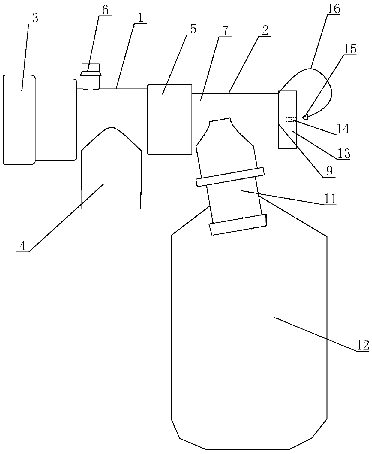
[0027] see Figure 1 to Figure 3 As shown, in this embodiment, a sputum collection device for artificial airway includes a trachea joint 1 and a sputum collection joint 2, and the trachea joint 1 includes an airway interface 3, a filter interface 4, a first connection interface 5 and a The medicine interface 6, the airway interface 3 is connected with an artificial airway capable of 360° free rotation, the filter interface 4 is equipped with a filter capable of 360° free rotation, and the medicine adding interface 6 is arranged on the top of the trachea joint 1, through adding The medicine interface 6 can administer medicine into the human body.

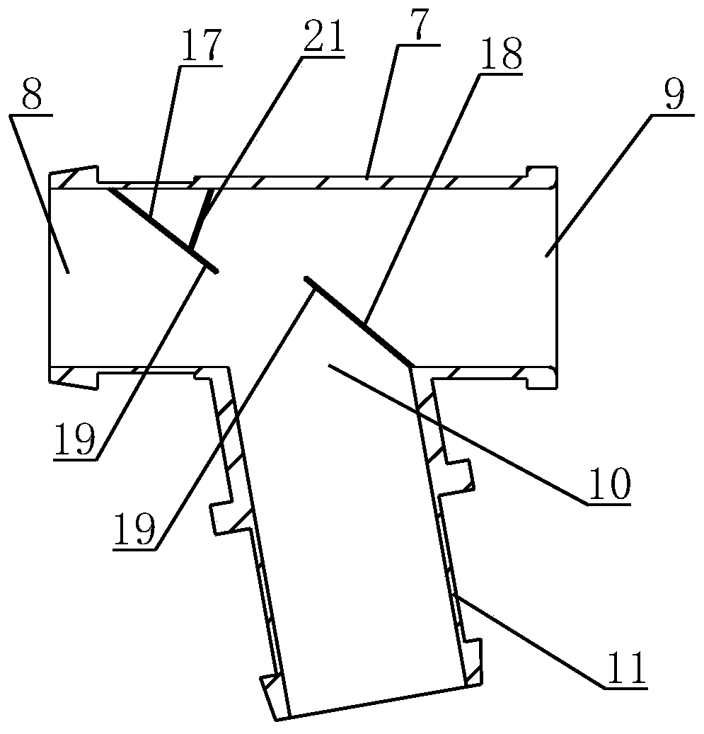
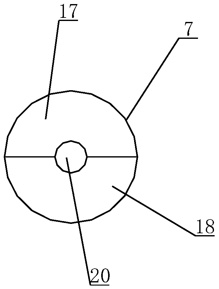
[0028] The sputum-collecting joint 2 adopts a T-shaped three-way structure, which includes a horizontal tube 7, one end of the horizontal tube 7 is used as the second connection interface 8, and the other end is used as the sputum suction tube access port 9, and the middle part of the horizontal tube 7 is provided with sputum The co...

Embodiment 2

[0031] see Figure 4 as shown, Figure 4 It is a cross-sectional view of the sputum-collecting joint of the sputum-collecting device for artificial airways provided by Embodiment 2 of the present invention.

[0032] The main difference between this embodiment and Embodiment 1 is that the setting of the baffle is different. In this embodiment, the sputum collection joint 2 is provided with an integral baffle 22 located on the side of the sputum collection interface 11 close to the inlet port 9 of the suction tube. , the center of the integral baffle 22 is provided with a sputum suction tube insertion hole 20, and the top of the integral baffle 22 near the side of the sputum suction tube access port 9 is provided with a guide for guiding the sputum suction tube into the sputum suction tube insertion hole 20 The slope 21 can guide the sputum suction tube entering the sputum collection joint 2 through the guide slope 21 so as to pass through the sputum suction tube insertion hole...


PUM


Abstract

The invention discloses a phlegm collecting device for an artificial airway. The phlegm collecting device comprises a trachea adapter and a phlegm collecting adapter, wherein the trachea adapter at least comprises an airway interface, a filter interface and a first connecting interface, the airway interface is connected with the artificial airway, a filter is mounted on the filter interface, the phlegm collecting adapter at least comprises a second connecting interface and a phlegm collecting interface, the first connecting interface is connected with the second connecting interface, a phlegmcollecting bag is detachably arranged on the phlegm collecting interface, an upper baffle and a lower baffle are arranged in the phlegm collecting adapter in a spaced manner, the upper baffle is located at one side, close to the second connecting interface, of the phlegm collecting interface, the lower baffle is located at one side, close to a phlegm sucking pipe access port, of the phlegm collecting interface, and semicircular grooves are separately formed in the bottom end of the upper baffle and the top end of the lower baffle. According to the phlegm collecting device, the operation is convenient, the universality is good, filter blockage of a sufferer cannot be caused, and much convenience is provided for use of the sufferer and medical treatment and nursing operations.

Description

technical field [0001] The invention belongs to the field of medical devices, in particular to a sputum collection device for artificial airways. Background technique [0002] Artificial airway is a gas channel established by inserting a catheter into the trachea through the upper respiratory tract or directly into the trachea. The artificial airway is an effective connection between the physiological airway and air or other gas sources to ensure the smoothness of the airway. To provide conditions for effective drainage, patency, mechanical ventilation, and treatment of lung diseases, the most common artificial airways are tracheal intubation (oral, nasal) and tracheotomy. [0003] During the use of the patient, the sputum produced in the respiratory tract will flow out of the artificial airway due to the patient's breathing or coughing. Since the artificial airway is directly connected to the external filter, the sputum will flow into the filter, resulting in tracheotomy. ...

Claims


Application Information

Patent Timeline
Patent Type & Authority Applications(China)
IPC IPC(8): A61M1/00A61M16/04A61M31/00
CPCA61M16/0402A61M16/0463A61M31/00A61M2210/1032A61M2210/005
Inventor 梁国骅池礼捷
Owner 江苏邦盛振业医疗器械有限公司
Learn More