Grooving and cutting tool and clamping assembly

A technology for cutting tools and clamping components, which is applied to the accessories of tool holders, tools for lathes, manufacturing tools, etc., and can solve the problems of difficulty in holding clamping devices, destroying grooves, and effort

Active Publication Date: 2021-04-16
GANZHOU ACHTECK TOOL TECH
View PDF5 Cites 0 Cited by
  • Summary
  • Abstract
  • Description
  • Claims
  • Application Information

AI Technical Summary

Problems solved by technology

The expensive cutting blade is clamped on the cutting blade, in this case, the thickness of the cutting blade is required to be smaller than that of the cutting blade, otherwise, the cutting blade will interfere with the groove formed by the cutting blade, destroying the groove
However, the current clamping method of the grooving and cutting tool has many defects. For example, US5803675 discloses a turning tool with a self-tensioning clamping finger, which has the following defects: 1. When changing the blade, it is easy to get stuck and become 2. It is difficult to maintain the clamping device in the open state, and it is easy to shift the matching position, resulting in the inability to successfully complete the insertion or removal of the tool; 3. The transformation of the deformation area into plastic deformation rather than elastic deformation is obvious. Risk, which in turn leads to damage to the tool or fixture; 4. The wear and tear between the various parts is severe, resulting in a short service life

Method used


Image

  • Grooving and cutting tool and clamping assembly
  • Grooving and cutting tool and clamping assembly
  • Grooving and cutting tool and clamping assembly

Examples


Embodiment Construction

[0038] The above content of the present invention will be further described in detail below through specific examples. However, it should not be understood that the scope of the above-mentioned subject matter of the present invention is limited only to the following examples. Without departing from the above-mentioned technical idea of ​​the present invention, various replacements or changes made according to ordinary technical knowledge and conventional means in this field shall be included in the scope of the present invention.

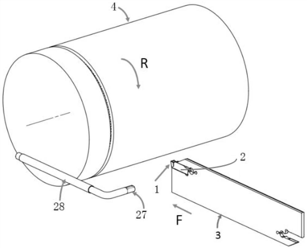
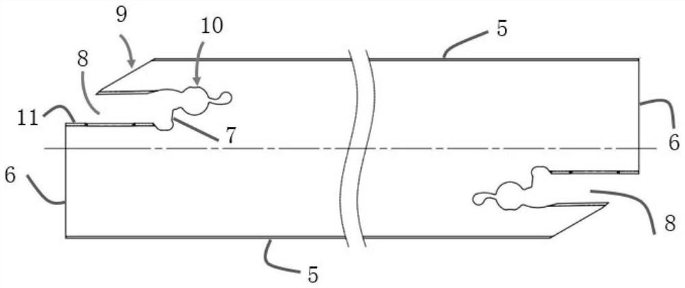
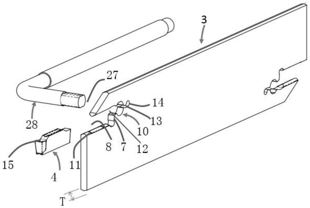
[0039] Such as Figure 1-7 As shown, a grooving and cutting tool and a clamping assembly include a tool 2, the tool is provided with a cutting edge 1, and the cutting edge 1 is specifically arranged on the tool seat 8 that will be described in detail later on at the front end of the tool 2 In this example, the front end of the cutting edge 1 is provided with a main cutting edge 15. In this embodiment, the main cutting edge 15 is formed on the upper...


PUM


Abstract

The invention discloses a grooving and cutting tool and a clamping assembly. The tool is put into the deformation hole of the knife plate through the clamping tool, and the user rotates the clamping tool. The cooperation between the clamping tool and the deformation hole makes the tip The elastic deformation reaches the open state, and the tool is put into or removed from the tool holder to achieve the effect of quick replacement, reduce the wear of the tool installation, and prolong the service life.

Description

technical field [0001] The invention belongs to the field of material processing, and in particular relates to a grooving and cutting tool clamping assembly. Background technique [0002] In metal turning, the workpiece is usually clamped on the machine tool and rotated around the central axis of the machine tool, and the cutting blade is fed along the radial direction of the machine tool to turn deep and narrow grooves on the workpiece or cut off the workpiece. When grooving, the cutting blade needs to be inserted into the workpiece at an appropriate depth to form a groove. At this time, the thickness of the cutting blade is the width of the groove. When cutting, not only the cutting blade needs to be inserted into the workpiece, but also the cutting blade needs to be inserted into the workpiece. near the central axis. The expensive cutting blade is clamped on the cutting blade, in this case, the thickness of the cutting blade is required to be smaller than that of the cut...

Claims


Application Information

Patent Timeline
Patent Type & Authority Patents(China)
IPC IPC(8): B23B29/00B23B27/00
CPCB23B27/00B23B29/00
Inventor 殷磊夏金林谭卓鹏曹昊铉黄常华李炜张国重
Owner GANZHOU ACHTECK TOOL TECH
Why Eureka
Try Eureka