Multi-clamp tool for piston connecting rod and operation method thereof

A technology of piston connecting rod and multiple fixtures, which is applied in the direction of clamping, positioning devices, manufacturing tools, etc., can solve the problems of low production efficiency and achieve the effect of improving production efficiency and reducing distance

Active Publication Date: 2020-06-05
上海通成企业发展有限公司
View PDF19 Cites 0 Cited by
  • Summary
  • Abstract
  • Description
  • Claims
  • Application Information

AI Technical Summary

Problems solved by technology

[0004] When machining the piston connecting rod of the automobile, it is usually processed by a CNC machining center. The above-mentioned tooling can only clamp and fix one connecting rod at a time for processing, and the production efficiency is low.

Method used


Image

  • Multi-clamp tool for piston connecting rod and operation method thereof
  • Multi-clamp tool for piston connecting rod and operation method thereof
  • Multi-clamp tool for piston connecting rod and operation method thereof

Examples


Embodiment 1

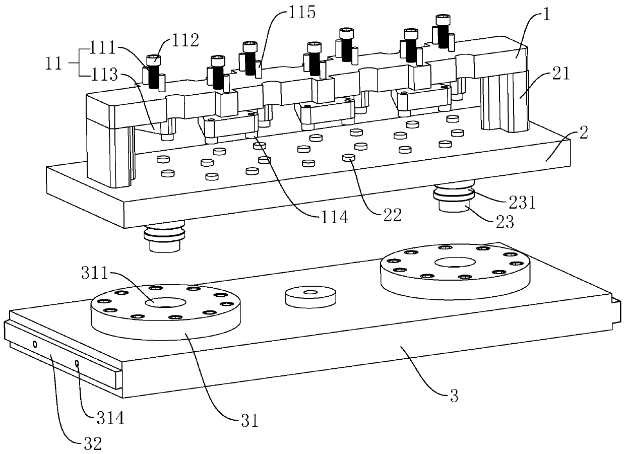
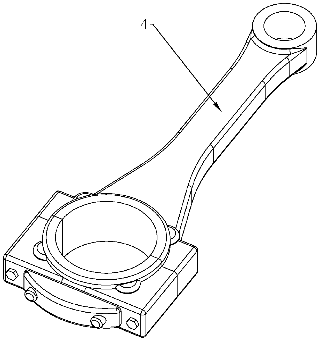
[0045] refer to figure 1 and image 3, is a multi-clamp tooling for piston connecting rods disclosed in the present invention, including a bottom plate 2, a cover plate 1 and a fixing seat 3 for connecting with a workbench of a numerical control machining center. The base plate 2 is detachably connected with the fixing seat 3, the top of the base plate 2 is provided with support columns 21 along the vertical direction at both ends of its length direction, the cover plate 1 is located directly above the base plate 2 and its two ends in the length direction are connected to two supports. Columns 21 are detachably connected by bolts. The cover plate 1 is provided with a plurality of clamps 11 for fixing the piston connecting rod 4 along its length direction, so that multiple piston connecting rods 4 can be fixed on the base plate 2 at the same time, and then the base plate 2 is fixed on the numerical control through the fixing seat 3 On the working table of the machining center...

Embodiment 2

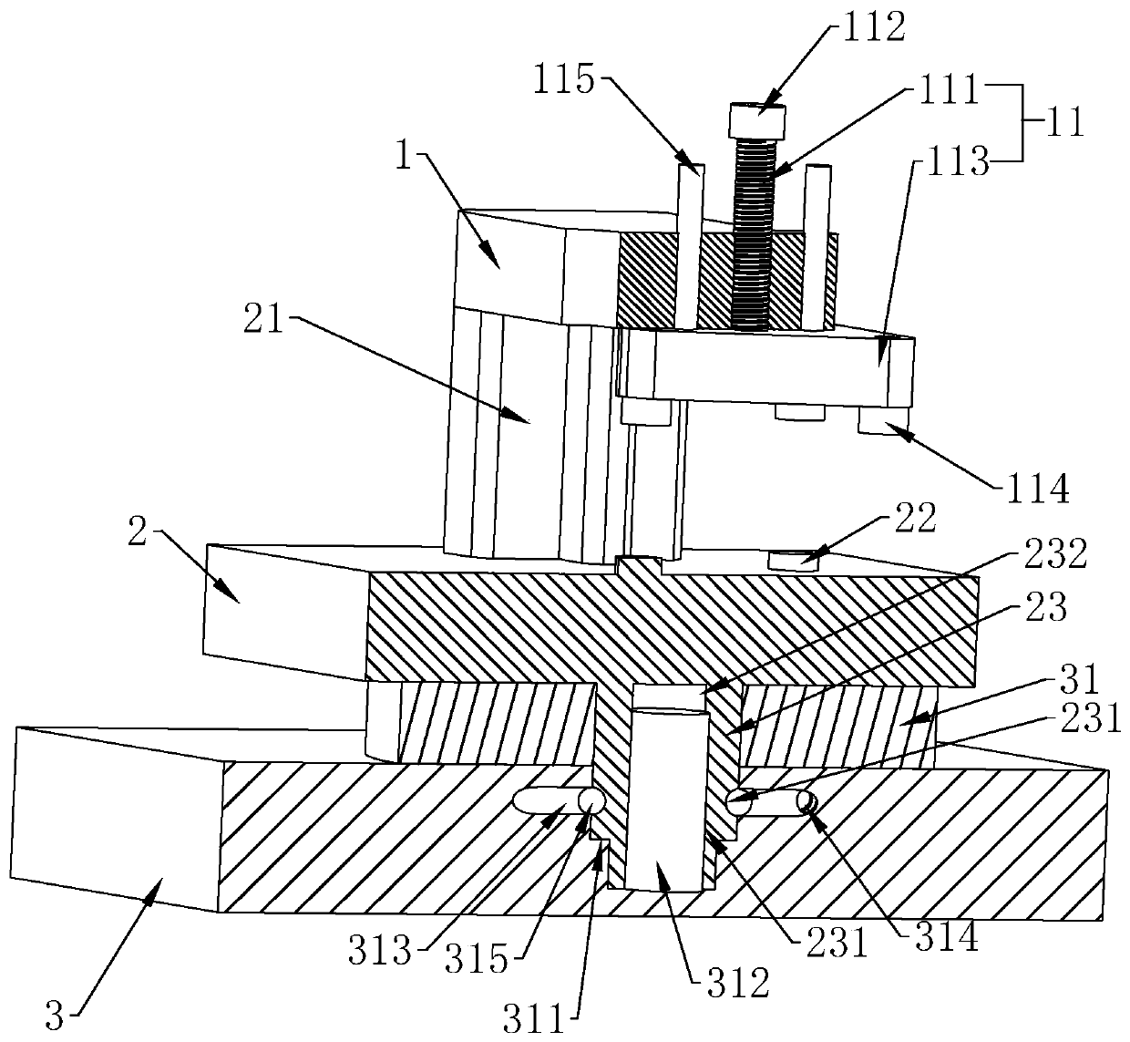
[0051] refer to figure 1 and figure 2 , a method of operating a multi-clamp tooling for a piston connecting rod applied in Embodiment 1, comprising the following steps:

[0052] S1: Fixing seat 3 is installed on the workbench of numerical control machining center;

[0053] That is, the card is embedded on the workbench of the numerical control machining center through the slide blocks 32 at both ends of the fixing seat 3. The workbench of the numerical control machining center is provided with two columns, and the opposite sides of the two columns are provided with chute, and the fixing seat 3 cards are embedded in the chute, and now the air outlet of the workbench in the chute is aligned with the air inlet of the air passage 314 at both ends of the holder 3.

[0054] S2: rotate the screw rod 111 by rotating the handle 112 to make the triangular pressing plate 113 rise in the vertical direction;

[0055] S3: The piston connecting rod 4 that will need to be processed (refer...


PUM


Abstract

The invention relates to a multi-clamp tool for piston connecting rods and an operation method of the multi-clamp tool. The multi-clamp tool comprises a base plate, a cover plate and a fixing base which is used for being connected with a workbench of a numerical control machining center. The base plate and the fixing base are detachably connected. Supporting columns are arranged in the vertical direction at the two ends of the top of the base plate in the length direction. The cover plate is located over the base plate, and the two ends of the cover plate in the length direction are detachablyconnected with the two supporting columns. Multiple clamps which are used for fixing the piston connecting rods are arranged on the cover plate in the length direction of the cover plate. The multi-clamp tool for the piston connecting rods has the advantages that the multiple clamps can fix the multiple piston connecting rods to the base plate, then the base plate is fixed to the workbench of thenumerical control machining center through the fixing base, the multiple piston connecting rods are simultaneously machined, and the effect that the production efficiency is improved is achieved.

Description

technical field [0001] The invention relates to the technical field of processing equipment for automobile piston connecting rods, in particular to a multi-clamp tooling for piston connecting rods and an operating method thereof. Background technique [0002] The piston is a reciprocating part in the cylinder block of an automobile engine. The basic structure of the piston can be divided into top, head and skirt. The top of the piston is the main part of the combustion chamber, and its shape is related to the selected form of the combustion chamber. Gasoline engines mostly use flat-top pistons, which have the advantage of small heat-absorbing areas. There are often various pits on the top of the piston of a diesel engine, and its specific shape, position and size must be adapted to the requirements of the mixture formation and combustion of the diesel engine. As a typical key automotive component, the piston has strong technological characteristics in cutting. The domest...

Claims


Application Information

Patent Timeline
IPC IPC(8): B23Q3/06
CPCB23Q3/061B23Q3/062
Inventor 任永军
Owner 上海通成企业发展有限公司
Why Eureka
Try Eureka