Thermal temperature rise compensating method for numerical-control machine tool

A CNC machine tool, heat and temperature technology, applied in metal processing mechanical parts, maintenance and safety accessories, measuring/indicating equipment, etc., can solve the problems of high price, error compensation, poor machining accuracy, etc., and achieve low-cost effects

Inactive Publication Date: 2020-06-05
广州义同机械实业有限公司
View PDF7 Cites 0 Cited by
  • Summary
  • Abstract
  • Description
  • Claims
  • Application Information

AI Technical Summary

Problems solved by technology

[0003] To solve this problem, the traditional solution is to measure the temperature rise change of the ball screw through the temperature sensor, and then calculate the positioning error value of the axis movement of the CNC machine tool according to the relative relationship between the deformation of each transmission part and the temperature change, and compensate it to the CNC machine tool. In the system, this method is to obtain the deformation of the transmission parts indirectly. Due to the limitation of the machine tool mechanism, it may not be able to truly reflect the deformation of the transmission parts, which may lead to wrong compensation and lead to poor machining accuracy.
Another traditional method to solve the temperature rise and deformation of the transmission parts of CNC machine tools is to use a hollow oil-cooled ball screw. The oil cooler is designed with an oil temperature compensation system to keep the temperature of the ball screw within a certain temperature range. Effectively control the temperature rise of the screw rod, but the price is expensive
Another transmission method to solve the temperature rise and deformation of the transmission parts of CNC machine tools is to convert the semi-closed-loop control machine tool into full-closed-loop control by adding a grating ruler, but the price is expensive, especially on large-scale CNC gantry machine tools. The cost ratio is very high

Method used


Image

  • Thermal temperature rise compensating method for numerical-control machine tool

Examples


Embodiment Construction

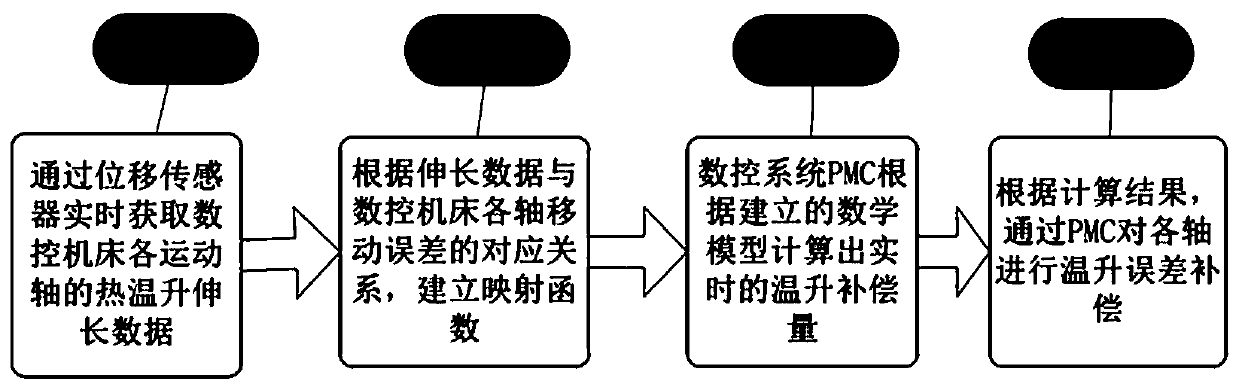
[0024] A: The elongation data of the ball screw under the thermal state of each motion axis is obtained in real time through the displacement sensor.

[0025] In step A, the thermal temperature rise of each moving axis will reach a saturation value, and in this case the measured value of the displacement sensor remains unchanged.

[0026] The method of step A can be used to pre-install displacement sensors on the CNC machine tool with the same structure to detect the elongation of the ball screw of each movement axis under the change of temperature rise.

[0027] B: According to the corresponding relationship between the elongation data of the ball screw and the movement error of each axis of the CNC machine tool under the thermal state of each movement axis, a mapping function between the two is established;

[0028] In step B, the actual displacement error variation of each axis of the CNC machine tool can be obtained by detecting the displacement variation of each motion ax...


PUM


Abstract

The invention discloses a thermal temperature rise compensating method for a numerical-control machine tool. In work of the numerical-control machine tool, a displacement sensor obtains elongation ofa rolling ball lead screw under each motion axis thermal temperature rise state of the numerical-control machine tool, and a corresponding mapping function is established according to a relationship between the elongation and a motion axis displacement error value; and a PMC system of a numerical-control system automatically calculates the error compensation value of each motion axis, and the numerical-control machine tool control system compensates motion axis displacement errors caused by thermal temperature rise. According to the thermal temperature rise compensating method disclosed by theinvention, the elongation of each motion axis lead screw thermal temperature rise is directly obtained by the displacement sensor, so that elongation data errors of rolling ball lead screw temperature rise are small, and precision is high; elongation data of the rolling ball lead screw temperature rise and the motion axis displacement error data are transmitted into the PMC of the numerical-control system to automatically calculate the error compensation value, and therefore, thermal temperature rise compensation precision is effectively improved, and product cost increase amount is smaller than 2%-3%. The method realizes solving the problems that processing precision of numerical-control equipment is reduced, a qualification rate of processed products is low, and the like as motion axispositioning errors are caused by motion axis transmission shaft deformation due to temperature changes with low cost.

Description

technical field [0001] The invention relates to the technical field of numerical control machine tools, and mainly relates to a method for compensating the precision of the numerical control machine tool for thermal temperature rise changes of the numerical control machine tool. Background technique [0002] When the CNC machine tool is working, there is relative motion between the transmission parts. The ball screw, ball screw nut, and bearing supporting the screw of the CNC machine tool will heat up under the action of friction, which will cause the moving parts, ball screw, ball The heat expansion and cold contraction of the screw nut will cause the change of the positioning error of the moving axis of the CNC machine tool. To solve the above problems, it is necessary to monitor the displacement of the thermal elongation of the moving parts, and calculate the positioning error value of the axis movement of the CNC machine tool according to the relationship between the dis...

Claims


Application Information

Patent Timeline
Patent Type & Authority Applications(China)
IPC IPC(8): B23Q11/00B23Q17/24
CPCB23Q11/00B23Q17/2452
Inventor 卢跃刘付伟夫胡培才王青君刘之亨李明冯保英
Owner 广州义同机械实业有限公司
Why Eureka
Try Eureka