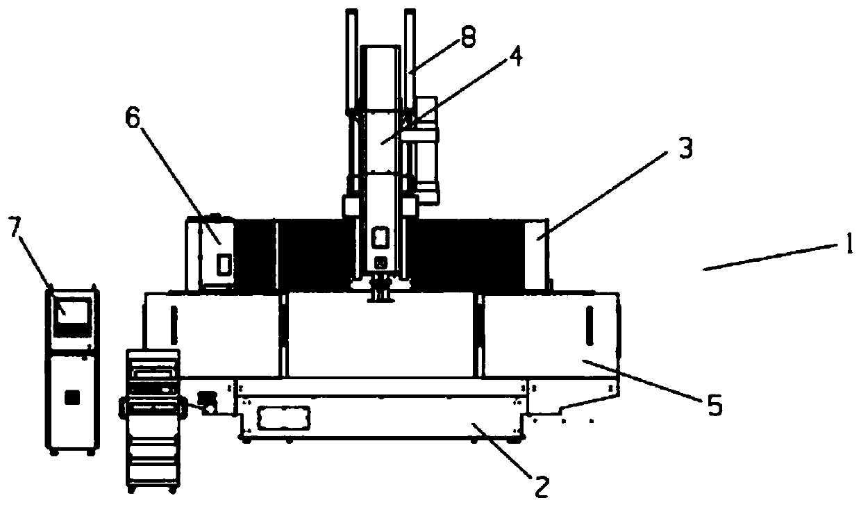
Gantry machining center with disc type tool magazine

A machining center and disc-type technology, applied in the direction of metal processing, metal processing equipment, metal processing machinery parts, etc., can solve the problems of low cost and slow processing speed of large CNC

Inactive Publication Date: 2020-06-05
广州德力数控设备有限公司
View PDF6 Cites 5 Cited by
  • Summary
  • Abstract
  • Description
  • Claims
  • Application Information

AI Technical Summary

Problems solved by technology

[0002] At present, in the large-stroke gantry-type CNC machining center, the processing speed is an important indicator to test a machine, and the speed of the large-scale machining centers on the market is generally not very high, especially many adopt the bamboo hat type and in-line The machining center of the type tool magazine, due to factors such as volume, material, structure, etc., leads to slow processing speed of large CNC machine tools, because improving the machining accuracy and speed of large CNC machine tools is a major difficulty in this field, and among large CNC machine tools, The structure of the gantry movement is the characteristic of this type of machine tool, because compared with the table movement, the volume is smaller and does not take up too much space. In terms of speed improvement, many hard conditions can no longer be changed, but the application of the tool magazine can be changed. Type to increase the tool change speed, thereby increasing the processing speed, especially necessary for applications with frequent tool changes

Method used


Image

  • Gantry machining center with disc type tool magazine
  • Gantry machining center with disc type tool magazine

Examples


Embodiment Construction

[0022] In the following description, numerous specific details are given in order to provide a more thorough understanding of the present invention. It will be apparent, however, to one skilled in the art that embodiments of the invention may be practiced without one or more of these details. In other examples, some technical features known in the art are not described in order to avoid confusion with the embodiments of the present invention.

[0023]In order to thoroughly understand the embodiments of the present invention, a detailed structure will be set forth in the following description. It is evident that practice of the embodiments of the invention is not limited to specific details familiar to those skilled in the art. Preferred embodiments of the present invention are described in detail below, however, the present invention may have other embodiments besides these detailed descriptions.

[0024] In the description of the present invention, the orientation or positi...


PUM


Abstract

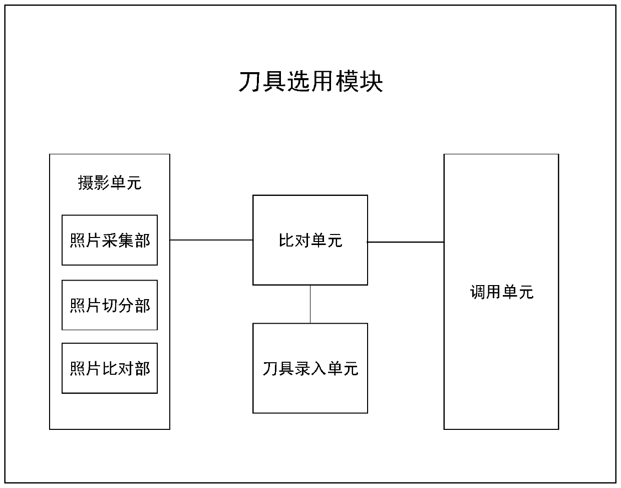
The invention provides a gantry machining center with a disc type tool magazine. A control system of the gantry machining center comprises a tool selecting module, wherein the tool selecting module comprises a photographing unit, a comparison unit, a tool recording unit and a calling unit; the photographing unit is used for photographing the information of a to-be-processed product and photographing the to-be-processed product to obtain the size information and the material information of the to-be-processed product; the tool recording unit is used for storing the information of the tools, anda staff inputs the material information, the hardness information and the machining precision information of each tool in the tool magazine into the tool recording unit; the comparison unit receivesthe information of the to-be-processed product from the photographing unit, and compares the received information of the to-be-processed product with the tool information stored in the tool recordingunit so as to carry out priority numbering on each tool stored in the tool recording unit; and the calling unit calls the tools in sequence according to the priority serial numbers of the tools.

Description

technical field [0001] The invention relates to the technical field of numerical control machine tools, in particular to a gantry machining center with a disc type tool magazine. Background technique [0002] At present, in the large-stroke gantry-type CNC machining center, the processing speed is an important indicator to test a machine, and the speed of the large-scale machining centers on the market is generally not very high, especially many adopt the bamboo hat type and in-line The machining center of the type tool magazine, due to factors such as volume, material, structure, etc., leads to slow processing speed of large CNC machine tools, because improving the machining accuracy and speed of large CNC machine tools is a major difficulty in this field, and among large CNC machine tools, The structure of the gantry movement is the characteristic of this type of machine tool, because compared with the table movement, the volume is smaller and does not take up too much spa...

Claims


Application Information

Patent Timeline
Patent Type & Authority Applications(China)
IPC IPC(8): B23Q37/00B23Q3/16
CPCB23Q3/16B23Q37/00
Inventor 王庆宏
Owner 广州德力数控设备有限公司
Why Eureka
Try Eureka