Hot mixing machine for plastic processing

A hot mixer and plastic technology, applied in the field of plastic processing, can solve the problems of affecting discharge, raw material cooling and solidification, bonding, etc., and achieve the effect of preventing clogging

Inactive Publication Date: 2020-06-05
杨保长
View PDF6 Cites 0 Cited by
  • Summary
  • Abstract
  • Description
  • Claims
  • Application Information

AI Technical Summary

Problems solved by technology

[0005] Aiming at the deficiencies in the prior art, the object of the present invention is to provide a thermomixer for plastic processing to solve the problem of the prior art because the plastic will generate temperature during the thermomixing process, and the raw materials will be melted and mixed, and the plastic raw materials have Viscous, when the raw materials need to be discharged after hot mixing is completed, due to the low temperature of the discharge pipe, initial cooling will occur when it contacts with the raw materials, causing part of the raw materials to cool and solidify, and then bonded to the inner wall of the discharge pipe In fact, when more and more substances are accumulated, it will cause the blockage of the discharge port, which will affect the problem of discharge.

Method used


Image

  • Hot mixing machine for plastic processing
  • Hot mixing machine for plastic processing
  • Hot mixing machine for plastic processing

Examples


Embodiment 1

[0027] Example 1: Please refer to Figure 1-Figure 5 , the specific embodiments of the present invention are as follows:

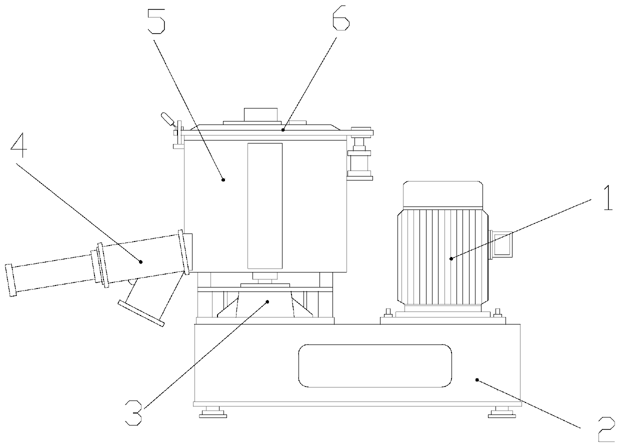
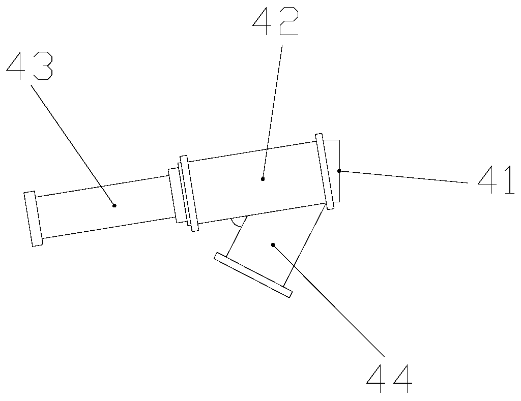
[0028] Its structure includes a motor 1, a transmission case 2, a drive seat 3, a discharge structure 4, a heat mixing tank 5, and an upper cover 6. The motor 1 is vertically installed on the upper end of the transmission case 2 and is mechanically connected. The drive seat 3 Installed on the right side of the upper end of the transmission case 2 and meshed inside, the hot mixing tank 5 is vertically installed on the upper end of the driving base 3 and located on the same axis, the upper cover 6 is arranged on the upper end of the hot mixing tank 5 and is mechanically connected, The discharge structure 4 is embedded and installed at the lower left end of the heat mixing tank 5 and connected inside; the discharge structure 4 includes a discharge port 41, a conduction structure 42, a drive motor 43, and a discharge pipe 44. The port 41 is located on the rig...

Embodiment 2

[0036] Example 2: Please refer to Figure 1-Figure 7 , the specific embodiments of the present invention are as follows:

[0037]Its structure includes a motor 1, a transmission case 2, a drive seat 3, a discharge structure 4, a heat mixing tank 5, and an upper cover 6. The motor 1 is vertically installed on the upper end of the transmission case 2 and is mechanically connected. The drive seat 3 Installed on the right side of the upper end of the transmission case 2 and meshed inside, the hot mixing tank 5 is vertically installed on the upper end of the driving base 3 and located on the same axis, the upper cover 6 is arranged on the upper end of the hot mixing tank 5 and is mechanically connected, The discharge structure 4 is embedded and installed at the lower left end of the heat mixing tank 5 and connected inside; the discharge structure 4 includes a discharge port 41, a conduction structure 42, a drive motor 43, and a discharge pipe 44. The port 41 is located on the righ...


PUM


Abstract

The invention discloses a hot mixing machine for plastic processing. The hot mixing machine for plastic processing structurally comprises a motor, a transmission case, a driving seat, a discharging structure, a hot mixing tank and an upper cover. The motor is vertically installed at the upper end of the transmission case, the driving seat is installed on the right side of the upper end of the transmission case, the hot mixing tank is vertically installed at the upper end of the driving seat, the upper cover is arranged at the upper end of the hot mixing tank, and the discharging structure is installed at the left lower end of the hot mixing tank in an embedded mode. The discharging structure comprises a discharging port, a conducting structure, a driving motor and a discharging pipe, the discharging port is formed in the right side of the conducting structure, the driving motor is installed on the left side of the conducting structure, and the discharging pipe is installed on the outersurface of the conducting structure in an inclined mode. According to the hot mixing machine for plastic processing, material scrapping plates are arranged on the outer sides of material conveying blades, the materials can be better scraped down when the materials stick to the inner wall, and it is avoided that the materials remain on the inner wall and accumulate overmuch to cause blocking; andelectric heating wires are arranged on the inner sides of the material conveying blades, the inner sides of the material conveying blades are maintained at the proper temperature, the raw materials are maintained in the melt state to be better conveyed, and then the raw materials are prevented from remaining to cause blocking.

Description

technical field [0001] The invention belongs to the field of plastic processing, and in particular relates to a thermal mixer for plastic processing. Background technique [0002] In plastic processing, because the raw materials have many different material compositions, they need to be mixed to better mix and process the raw materials to provide guarantee for the production and processing of plastics, so it is necessary to use a thermomixer, and a thermomixer It can also be used for color mixing of plastics, premixing during preparation of materials and ingredients, and pretreatment for plastic processing, but the prior art has the following deficiencies: [0003] Because the temperature of the plastic will be generated during the hot mixing process, the raw materials will be melted and mixed, and the plastic raw materials are viscous. , Preliminary cooling will occur, causing part of the raw materials to cool and solidify, and then stick to the inner wall of the discharge...

Claims


Application Information

Patent Timeline
Patent Type & Authority Applications(China)
IPC IPC(8): B29B7/10B29B7/22B29B7/24B29B7/26B29B7/82
CPCB29B7/10B29B7/22B29B7/24B29B7/26B29B7/826
Inventor 杨保长
Owner 杨保长
Why Eureka
Try Eureka