Heat dissipation mechanism for gear grinding machine

A technology of heat dissipation mechanism and grinding machine, which is applied to the parts of grinding machine tools, cleaning methods using tools, grinding machines, etc. It can solve the problems of affecting the efficiency of grinding, requiring high precision of tooth surfaces, and burning out grinding devices, etc., to achieve Improve grinding efficiency, reduce grinding cost and improve grinding quality

Active Publication Date: 2022-01-28
CHONGQING RUNYUE MACHINERY CO LTD
View PDF8 Cites 0 Cited by
  • Summary
  • Abstract
  • Description
  • Claims
  • Application Information

AI Technical Summary

Problems solved by technology

[0002] In the rapid development of the current industry, the use of gears has become particularly frequent. A large number of various gear transmissions are used in almost all industries. The current gears are generally used in the transmission of heavy industries. For The precision of the tooth surface of the gear is high, so it is necessary to carry out fine grinding on the tooth surface of the gear. When the gear is polished, a lot of heat will be generated. If the heat is not dissipated in time, the grinding device will be burned out and the grinding efficiency will be affected. Therefore, when the gear is grinding It is often necessary to add water, but if you add water for grinding during the grinding process, you need to stop the grinding device, which affects the efficiency of grinding and is not convenient enough

Method used


Image

  • Heat dissipation mechanism for gear grinding machine
  • Heat dissipation mechanism for gear grinding machine
  • Heat dissipation mechanism for gear grinding machine

Examples


Embodiment 1

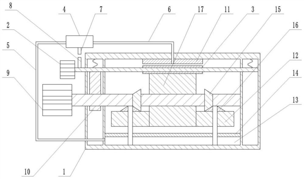
[0029] Embodiment 1 is basically as attached Figure 1-2 Shown:

[0030] A heat dissipation mechanism of a gear 17 grinding machine comprises a frame 1, a grinding device and a heat dissipation device, and the grinding device is arranged on the frame 1.

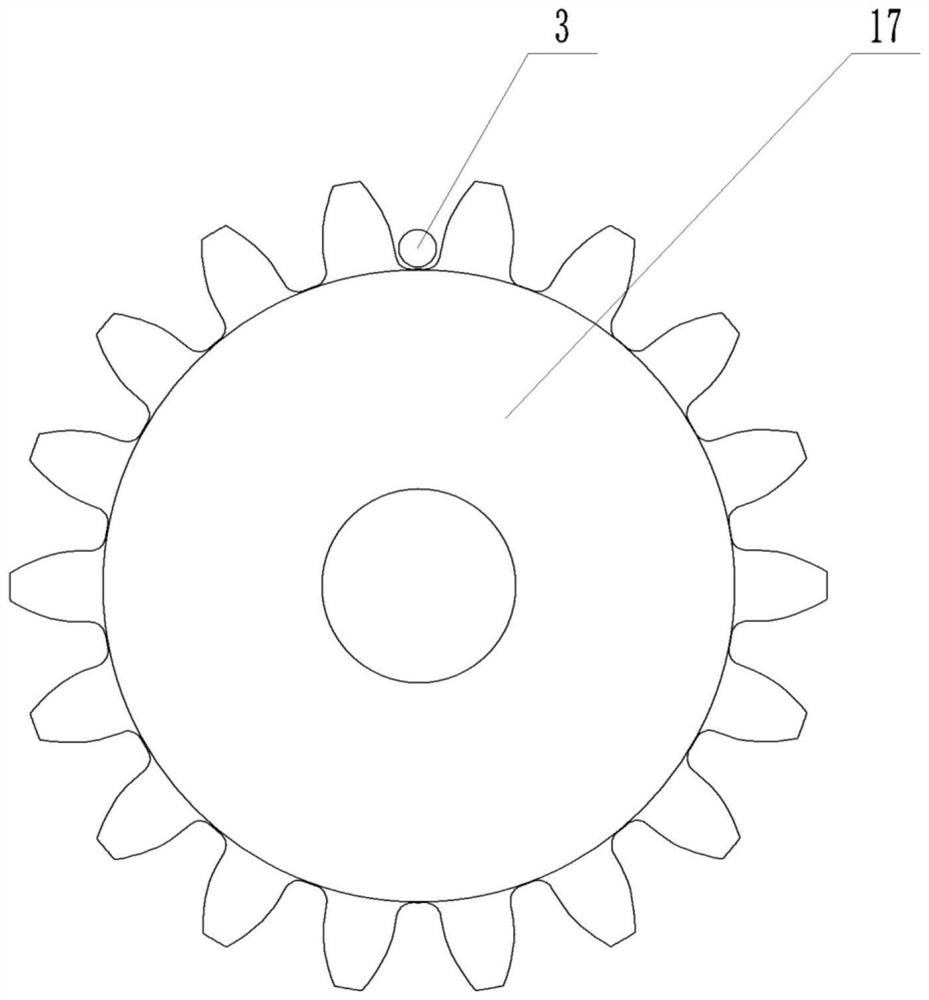
[0031] The grinding device comprises a first rotating motor 2 and a teeth grinding roller 3, the first rotating motor 2 is fixedly arranged on the frame 1, and the output shaft two ends of the first rotating motor 2 are rotatably arranged on the frame 1, and the teeth grinding roller 3 is fixed on the output shaft, the diameter of the tooth grinding roller 3 is larger than that of the output shaft, the tooth grinding roller 3 is coaxially arranged with the output shaft, and the diameter of the tooth grinding roller 3 matches the tooth root of the gear 17;

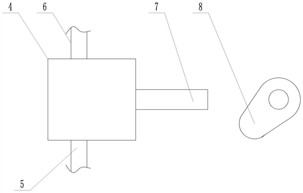
[0032] as attached Figure 3-4 Shown:

[0033] The cooling device includes a water cylinder 4, a water inlet pipe 5 and a water outlet pipe 6. The water cylinder 4 slid...

Embodiment 2

[0045] The difference between this embodiment 2 and embodiment 1 is that, as attached Figure 5 Shown:

[0046] It also includes a storage mechanism. The storage mechanism includes a storage rack 18 and a moisture monitoring assembly. The storage rack 18 is sequentially provided with a storage frame 19 for storing gear workpieces from top to bottom.

[0047] Moisture monitoring assembly is located at the top of storage rack 18, and moisture monitoring assembly includes casing 20, oil pot 21, water absorption drying box 22, load-bearing plate 23, pressure sensor 26 and single-chip microcomputer, and oil pot 21 and load-bearing plate 23 are all arranged on casing 20 Above, the water-absorbing drying box 22 is slidingly arranged on the box body 20, and the water-absorbing drying box 22 and the bearing plate 23 are connected by a spring. Matching pressure switch 25, the pressure switch 25 is used to control the energization of the pressure sensor 26, the pressure sensor 26 is arr...


PUM


Abstract

The invention belongs to the technical field of gear grinding devices, and particularly relates to a heat dissipation mechanism for a gear grinding machine. The heat dissipation mechanism comprises a rack, a grinding device and a heat dissipation device, wherein the grinding device is arranged on the rack; the grinding device comprises a first rotating motor and a tooth grinding roller; the first rotating motor is fixedly arranged on the rack; two ends of an output shaft of the first rotating motor are rotationally arranged on the rack; the tooth grinding roller is fixedly arranged on the output shaft; a diameter of the tooth grinding roller is larger than that of the output shaft; the tooth grinding roller and the output shaft are coaxially arranged; and the diameter of the tooth grinding roller is matched with a tooth root of a gear. According to the scheme, by arranging a cooling device, when the tooth grinding roller grinds the gear, water in a water outlet pipe flows out to directly cool the tooth grinding roller in time, so that the tooth grinding roller cannot be burnt out due to continuous grinding, the grinding does not need to be stopped due to cooling, and the grinding efficiency is further improved.

Description

technical field [0001] The proposal belongs to the technical field of gear grinding devices, and in particular relates to a heat dissipation mechanism for a gear grinding machine. Background technique [0002] In the rapid development of the current industry, the use of gears has become particularly frequent. A large number of various gear transmissions are used in almost all industries. The current gears are generally used in the transmission of heavy industries. For The precision of the gear tooth surface is high, so it is necessary to carry out fine grinding on the gear tooth surface. When the gear is polished, a lot of heat will be generated. If the heat is not dissipated in time, the grinding device will be burned out and the grinding efficiency will be affected. Therefore, when the gear is grinding It is often necessary to add water, but if water is added during the grinding process, the grinding device needs to be stopped, which affects the efficiency of grinding and ...

Claims


Application Information

Patent Timeline
Patent Type & Authority Applications(China)
IPC IPC(8): B24B19/00B24B41/06B24B47/12B24B41/04B24B55/03B24B53/00B08B1/02
CPCB24B19/00B24B41/06B24B47/12B24B41/04B24B55/03B24B53/00B08B1/20B08B1/165Y02P70/10
Inventor 曾义杰
Owner CHONGQING RUNYUE MACHINERY CO LTD
Why Eureka
Try Eureka