
360-degree rotating heavy transfer vehicle

A transfer vehicle, heavy-duty technology, applied in the direction of motor vehicles, vehicle maintenance, shunting equipment, etc., can solve the problems of limited height, narrow space, difficult transfer, etc.

Pending Publication Date: 2020-06-05
ZHEJIANG ZHENENG ELECTRIC POWER
View PDF8 Cites 0 Cited by
  • Summary
  • Abstract
  • Description
  • Claims
  • Application Information

AI Technical Summary

Problems solved by technology

[0005] The purpose of the present invention is to overcome the problem of difficult transfer of large equipment in existing power plants due to narrow space and limited height, and to provide a 360-degree rotating heavy-duty transfer vehicle with simple structure, convenient use and strong versatility

Method used


Image

  • 360-degree rotating heavy transfer vehicle
  • 360-degree rotating heavy transfer vehicle
  • 360-degree rotating heavy transfer vehicle

Examples


Embodiment 1

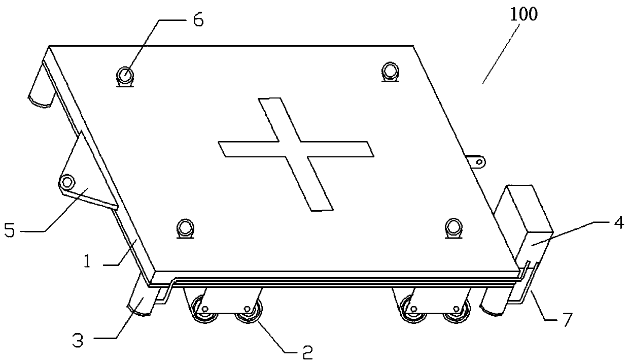
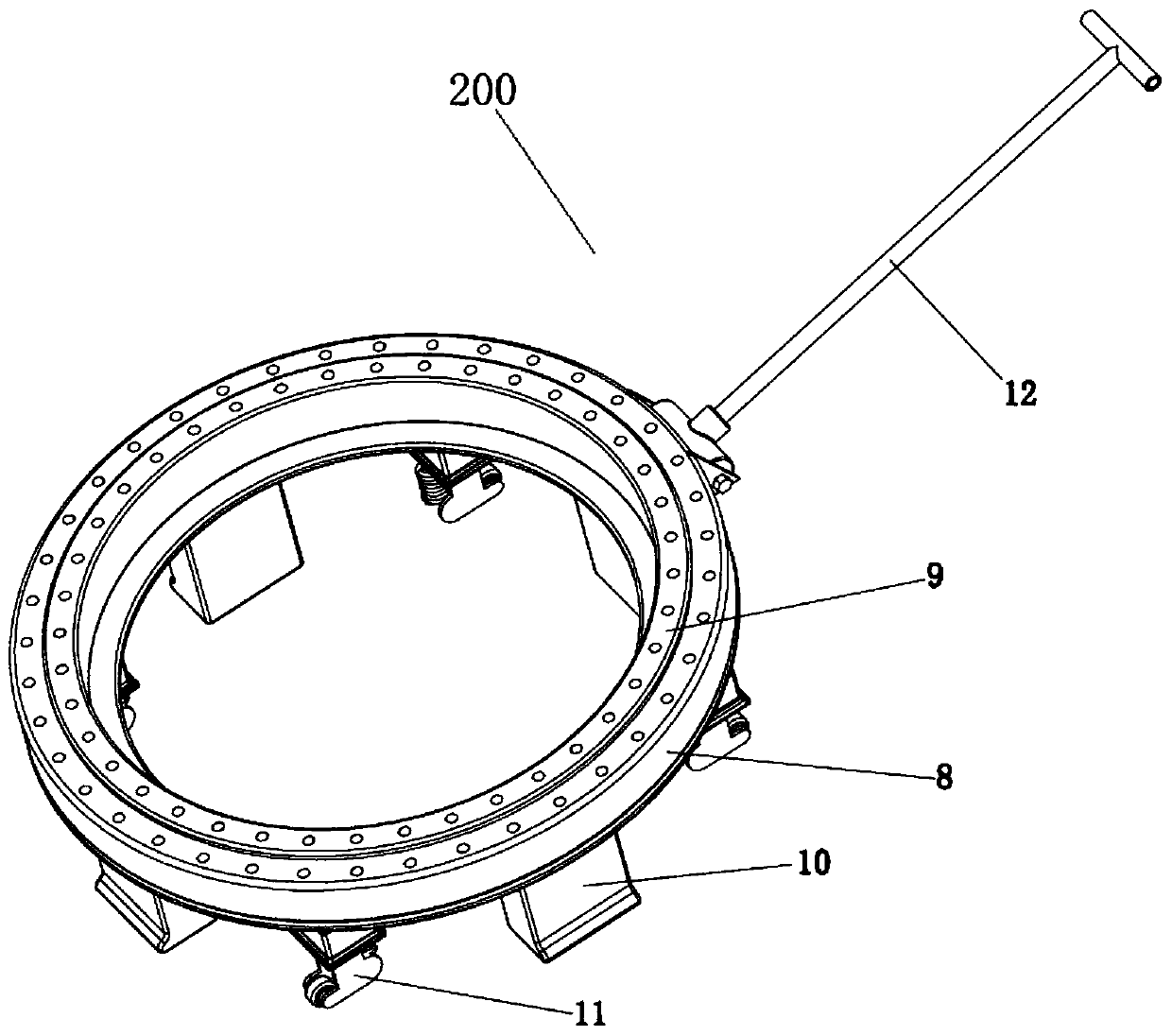
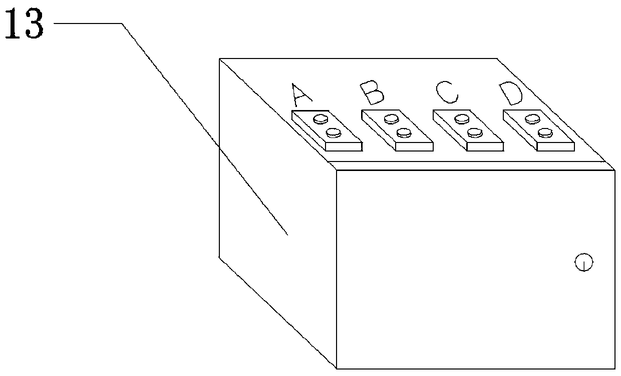
[0040] Such as Figures 1 to 5 As shown, a 360-degree rotating heavy-duty transfer vehicle includes a trolley body 100, a turntable 200 for 360° rotation of the trolley body, and an electro-hydraulic pump station 13; the trolley body 100 includes a trolley load platform 1, wheels 2 , a jack 3, a hydraulic station 4 and an oil pipeline 7; a plurality of wheels 2 are arranged under the trolley load platform 1, and at least one jack 3 is arranged near each of the wheels 2; each of the jacks 3 is respectively The hydraulic station 4 is communicated with the hydraulic station 4 through the oil pipeline 7; the hydraulic station 4 is connected with the electric hydraulic pump station 13; the hydraulic station 4 is provided with a hydraulic pressure relief valve;

[0041] The turntable 200 includes a turntable 8, a rotating ring 9, a support block 10 and a spring wheel 11; the turning ring 9 can rotate relative to the turntable 8, and the upper surface of the turning ring 9 is higher ...

Embodiment 2

[0043] Such as Figures 1 to 5 As shown, a 360-degree rotating heavy-duty transfer vehicle includes a trolley body 100, a turntable 200 for the trolley body to rotate 360°, and an electro-hydraulic pump station 13;

[0044] The trolley main body 100 includes a trolley load platform 1, wheels 2, jack 3, hydraulic station 4 and oil pipeline 7;

[0045] A plurality of wheels 2 are arranged under the trolley load platform 1, and at least one jack 3 is arranged near each wheel 2;

[0046] In practical applications, in order to better ensure that the trolley-carrying platform 1 runs smoothly and keeps it level as much as possible, at least three wheels 2 are provided at a time, preferably an even number greater than or equal to 4, and they are symmetrically distributed, so that it can be more Ensure that the trolley load platform 1 runs smoothly and keep it level as much as possible; the setting of the jack 3 is the same; with the ground, the connection mode of the wheel 2 and the ...


PUM


Abstract

The invention discloses a 360-degree rotating heavy transfer vehicle which comprises a trolley body, a rotary table allowing the trolley body to rotate by 360 degrees and an electric hydraulic pump station. The trolley body comprises a trolley loading platform, wheels, a jack, a hydraulic station and an oil way pipeline. A plurality of wheels and jacks are arranged below the trolley loading platform; each jack is communicated with the hydraulic station through an oil pipeline; the hydraulic station is connected with the electric hydraulic pump station; the rotary table comprises a rotary pedestal, a rotary ring, a supporting block and a spring wheel. The rotating ring can rotate relative to the rotary pedestal, and the upper surface of the rotating ring is higher than the upper surface ofthe rotary pedestal; and a plurality of spring wheels and supporting blocks are arranged below the rotary pedestal. The 360-degree rotating heavy transfer vehicle has the advantages of being small inwidth, low in height, high in stability and large in load capacity.

Description

technical field [0001] The invention relates to the field of transportation equipment, in particular to transportation equipment capable of transferring various large motors and components from places with narrow spaces and limited heights, and more specifically to a 360-degree rotating heavy-duty transfer vehicle. Background technique [0002] With the increase of the capacity of the unit assembly and the desulfurization and denitrification transformation of the unit, the arrangement of the equipment of the unit is becoming more and more compact, and the tonnage of the equipment is large, which far exceeds the transportation capacity of our factory's forklift trucks, etc., and the transportation of the equipment The lifting work in the process of inspection or overall replacement has the problem of narrow space and limited height. [0003] At present, the traditional method of manufacturing transport rack rollers is used for large-scale equipment transfer. Due to the huge w...

Claims


Application Information

Patent Timeline
Patent Type & Authority Applications(China)
IPC IPC(8): B62D59/02B60S9/10B60S13/02
CPCB62D59/02B60S9/10B60S13/02
Inventor 严刚俞刚萧猛孙春伟陶国平陆松宣振纲
Owner ZHEJIANG ZHENENG ELECTRIC POWER
Learn More