
Suspension bridge stiffening girder

A technology for stiffened beams and suspension bridges, applied to suspension bridges, bridges, bridge parts, etc., can solve problems affecting sight distance, inconvenient traffic organization, damage, etc., and achieve the effect of improving safety and wind resistance stability

Pending Publication Date: 2020-06-05
CHINA RAILWAY ENG CONSULTING GRP CO LTD
View PDF0 Cites 0 Cited by
  • Summary
  • Abstract
  • Description
  • Claims
  • Application Information

AI Technical Summary

Problems solved by technology

[0003] like figure 1 As shown, in the prior art, the upper stabilizing plate 100 and the lower stabilizing plate 100' are generally arranged above or below the bridge deck 200, which is an important means of wind resistance, which can significantly increase the critical wind speed of flutter, but at the same time also has the function of shielding Driving line of sight, affecting sight distance, inconvenient for traffic organization, vulnerable to damage, etc.

Method used


Image

  • Suspension bridge stiffening girder
  • Suspension bridge stiffening girder
  • Suspension bridge stiffening girder

Examples


Embodiment 1

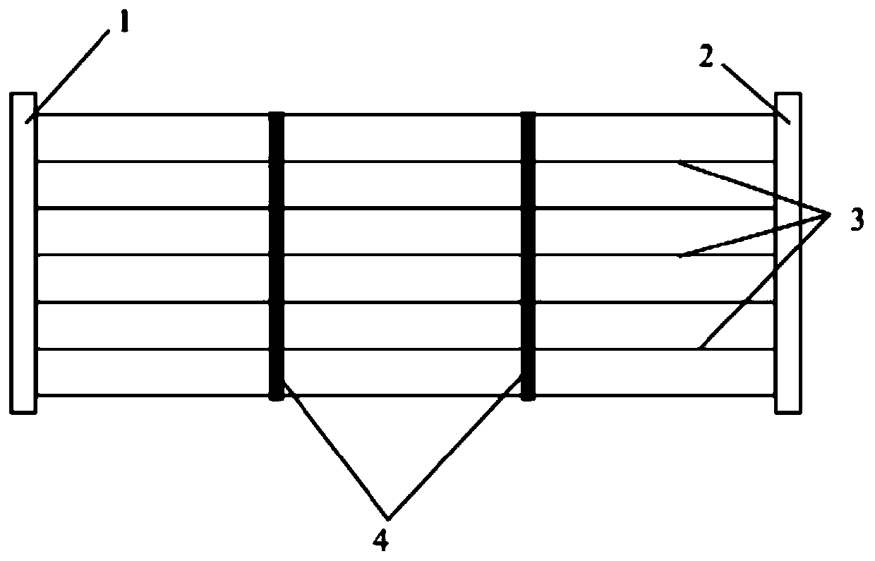
[0027] figure 2 As shown, the invention provides a suspension bridge stiffening beam, which includes:

[0028] The first main longitudinal beam 1, which is arranged on one side of the concrete bridge deck and runs through the entire bridge;

[0029] The second main longitudinal beam 2 is set on the other side of the concrete bridge deck and runs through the entire bridge;

[0030] And at least one beam 3 (which may preferably be a steel beam), which is arranged under the concrete bridge deck along the transverse direction; and one end of each beam is connected to the first main longitudinal beam 1, and the other end is connected to the The second main longitudinal beam 2; image 3 As shown, in this embodiment, the beams 3 have several tracks, and the spacing between the beams 3 is 2-5m (preferably 3m).

[0031] Further, the first main longitudinal beam 1 is provided with first hanging points 11 for connecting the sling 400 at even intervals along the longitudinal direction (that is,...

Embodiment 2

[0035] The difference between this embodiment and embodiment 1 is only that, as figure 2 As shown, the suspension bridge stiffening beam in this embodiment also includes:

[0036] A crash barrier 5, which is connected to the center and / or ends of the beam 3;

[0037] The first tuyere 6 is connected to the first main longitudinal beam 1;

[0038] The second tuyere 7 is connected to the second main longitudinal beam 2;

[0039] The pedestrian passage 8 is arranged on the first air nozzle 6 and / or the second air nozzle 7;

[0040] And a protective fence 9, which is arranged on one or both sides of the pedestrian passage 8 to ensure the safety of walking.

[0041] Therefore, in this embodiment, a tuyere is provided to further improve the aerodynamic performance of the section and increase the wind resistance of the bridge section.

[0042] In summary, the invention is a suspension bridge stiffening beam structure with an open bottom. By reasonably setting the number and spacing of secondary ...


PUM


Abstract

The invention discloses a suspension bridge stiffening beam which comprises a first main longitudinal beam which is longitudinally arranged along one side of a concrete bridge deck slab, a second mainlongitudinal beam which is longitudinally arranged along the other side of the concrete bridge deck slab, at least one cross beam which is arranged below the concrete bridge deck slab along the transverse bridge direction; and one end of each cross beam is connected with the first main longitudinal beam, and the other end of each cross beam is connected with the second main longitudinal beam. Thesuspension bridge stiffening beam can improve the wind-resistant stability of a bridge, and can also be used as a substitute wind-resistant means when a central stabilizing plate is inconvenient to arrange above a bridge deck.

Description

Technical field [0001] The invention relates to the field of bridge engineering, in particular to a suspension bridge stiffening beam. Background technique [0002] Suspension bridges have large spans, low structural rigidity, and are more sensitive to wind effects. Generally, the calculated flutter stability index is very high, and the flutter stability problem is more prominent. Therefore, when conducting wind resistance research on suspension bridges, wind resistance structural measures such as central stabilizers, deflectors, and air nozzles are generally set to ensure the wind resistance stability and safety of the bridge during construction and after completion and operation. [0003] Such as figure 1 As shown, in the prior art, the upper stabilizer plate 100 and the lower stabilizer plate 100' are generally arranged above or below the bridge deck 200. They are an important wind resistance measure, which can significantly increase the critical wind speed of flutter, but also ...

Claims


Application Information

Patent Timeline
IPC IPC(8): E01D19/00E01D11/02E01D19/10
CPCE01D11/02E01D19/00E01D19/103
Inventor 徐升桥金令邹永伟李国强高静青杨永明赵博孟庆涛李先婷
Owner CHINA RAILWAY ENG CONSULTING GRP CO LTD
Learn More