Rechargeable battery

a rechargeable battery and battery technology, applied in the field of rechargeable batteries, can solve the problems of destroying rechargeable batteries, unable to function properly, and unable to meet the needs of use, so as to improve the structure of a safety devi

Inactive Publication Date: 2006-05-04
SAMSUNG SDI CO LTD
View PDF1 Cites 12 Cited by
  • Summary
  • Abstract
  • Description
  • Claims
  • Application Information

AI Technical Summary

Benefits of technology

[0012] The present invention provides a rechargeable battery that maintains the internal pressure at a predetermined level by improving the structure of a safety device.

Problems solved by technology

However, gas is generated by chemical reactions that occur inside a rechargeable battery and may cause an explosion and combustion if the internal pressure increases beyond a predetermined level.
However, a problem with the above pressure-releasing valve is that once the pressure-releasing valve ruptures beyond its level of sustainable pressure, the rechargeable batteries are ruined due to air and moisture inflow from the outside through the opening.
Accordingly, the rechargeable battery loses its air-tight property and can no longer function properly.
In general, this problem leads to a shorter battery lifespan.
In particular, when the rechargeable batteries have a large power storage capacity for driving motors such as those in electric vacuums, electric scooters, electric vehicles, or hybrid electric automobiles, larger energy output and larger power storage capacity are required.
When the pressure-releasing valve ruptures following a change in internal pressure, sufficient high energy output is not obtained.

Method used


Image

  • Rechargeable battery
  • Rechargeable battery
  • Rechargeable battery

Examples


first embodiment

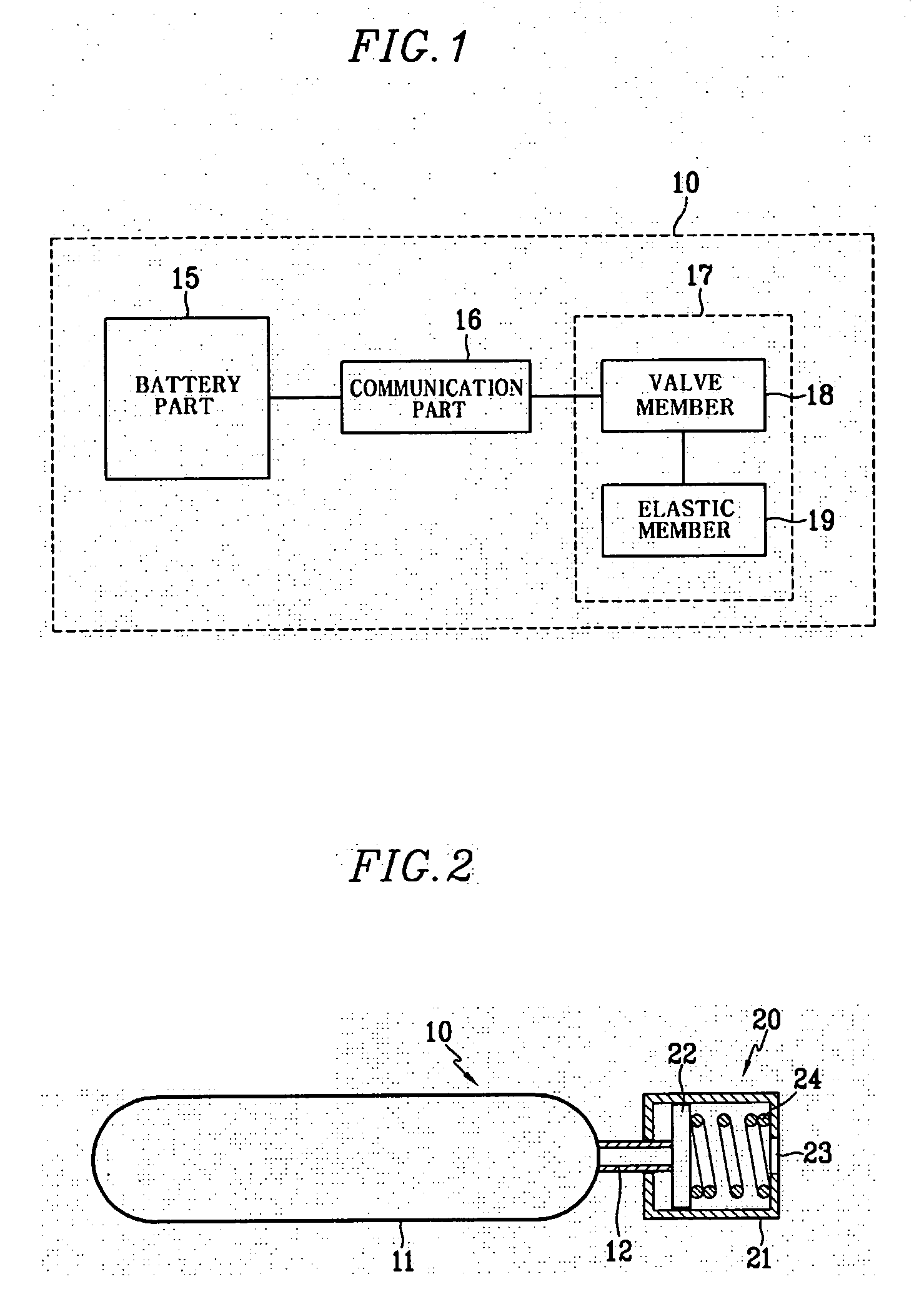
[0028]FIG. 1 is a schematic diagram of a rechargeable battery according to the present invention.

[0029] According to FIG. 1, a rechargeable battery 10 of the present invention includes a battery part 15 that generates electricity, a communication part 16, a unidirectional valve assembly 17 comprising a valve member 18, and an elastic member 19.

[0030] The battery part 15 includes elements that are capable of charging and discharging a battery. One side of the battery part 15 is coupled with the communication part 16, which is open to connect with the outside. The communication part 16 may take a variety of forms such as a hole, a tube, or a pipe. In addition, one side of the communication part 16 is coupled with the unidirectional valve assembly 17 for controlling, closing, and opening the communication part 16.

[0031] The unidirectional valve assembly 17 contains a valve member 18 that closes the communication part 16, an elastic member 19 that supports the valve member 18 by press...

second embodiment

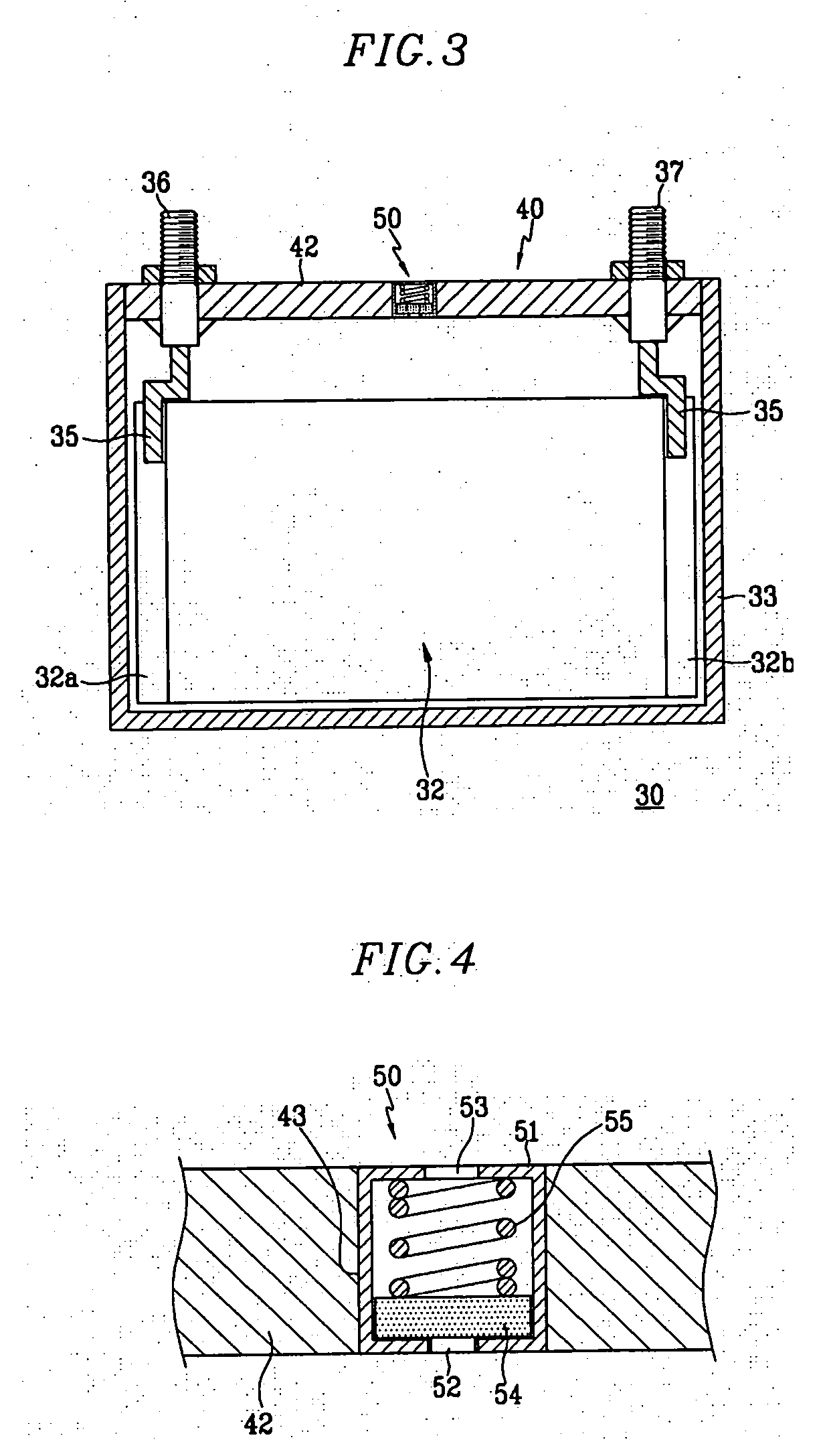
[0041]FIG. 3 and FIG. 4 illustrate a rechargeable battery according to the present invention.

[0042] As shown in FIG. 3, a rechargeable battery 30 includes an electrode assembly 32 comprising a positive electrode and a negative electrode with a separator interposed therebetween, a rectangular-box case 33 with a space for housing the electrode assembly 32, and a cap assembly 40 that is mounted on the opening of the case 33 to close it tightly. In addition, a positive terminal 36 and a negative terminal 37 are coupled with the electrode assembly 32 through tabs 35 that protrude out of the cap assembly 40, and a unidirectional valve assembly 50 is installed on the cap assembly 40 to maintain the internal pressure of the battery.

[0043] The case 33 may comprise conductive metals such as aluminum, aluminum alloy, or nickel-plated steel, for example. Also, the case 33 may be formed as a hexagon with an internal space for housing the electrode assembly 32.

[0044] According to this embodimen...

third embodiment

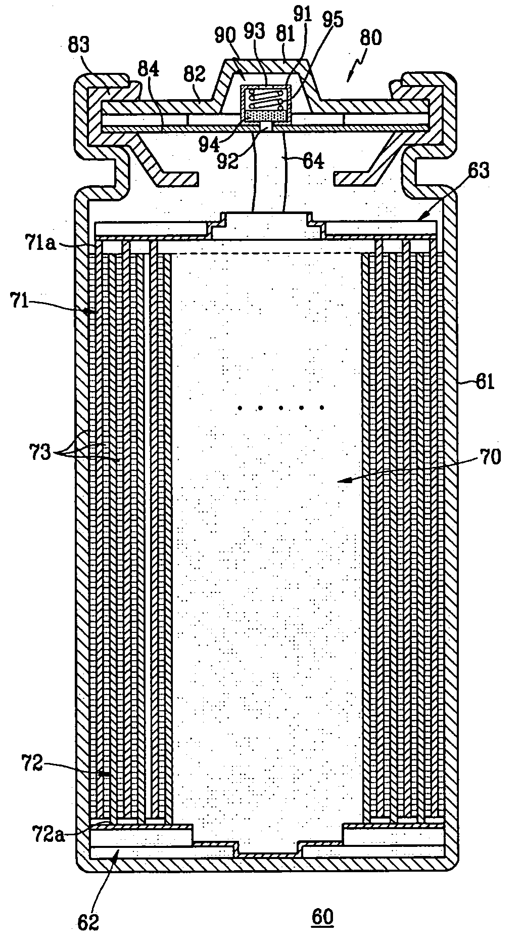
[0053]FIG. 5 shows a rechargeable battery according to the present invention.

[0054] As shown in FIG. 5, a rechargeable battery 60 includes an electrode assembly 70 comprising a positive electrode 71, a negative electrode 72, a separator 73 interposed between the electrodes, a cylindrical case 61 for housing the electrode assembly 70, a cap assembly 80 that is mounted on the upper end of the opening of a case 61 through a gasket 83 that seals the case 61, and a unidirectional valve assembly 90 that is installed into the cap assembly 80 to stably maintain the internal pressure of the battery.

[0055] Here, the electrode assembly 70 is formed in a jelly-roll configuration by winding the two electrodes with a positive uncoated region 71a and a negative uncoated region 72a opposite each other at both ends of the electrode assembly 70 with a separator therebetween.

[0056] The electrode assembly 70 of an embodiment of the present invention is housed in the case 61 with the positive uncoated...


PUM

PropertyMeasurementUnit
internal pressureaaaaaaaaaa
atmospheric pressureaaaaaaaaaa
internal pressureaaaaaaaaaa

Abstract

A rechargeable battery includes an electrode assembly comprising a positive electrode, a negative electrode, and a separator interposed in between the electrodes, a case that houses the electrode assembly, and a unidirectional valve assembly that is installed at a side of the case, is connected through with the inside of the case, and releases gas only from the inside to the outside.

Description

CROSS-REFERENCE TO RELATED APPLICATION [0001] This application claims priority to and the benefit of Korean Patent Application No. 10-2004-0086611, filed on Oct. 28, 2004, which is hereby incorporated by reference for all purposes as if fully set forth herein. BACKGROUND OF THE INVENTION [0002] 1. Field of the Invention [0003] The present invention relates to a rechargeable battery with an extended lifespan by maintaining a pressure inside a case at a predetermined level. [0004] 2. Description of the Background [0005] Generally, rechargeable batteries can be repeatedly charged and discharged unlike nonrechargeable batteries which cannot be recharged. High power rechargeable batteries that have a high energy density and use a non-aqueous electrolyte have recently been developed. Low-capacity batteries that include a single battery cell that is packaged in the form of a pack are used as a power source for small portable electronic devices such as mobile phones, laptop computers, and c...

Claims


Application Information

Patent Timeline
Patent Type & Authority Applications(United States)
IPC IPC(8): H01M2/12H01M2/08H01M2/04
CPCH01M2/1229H01M50/325Y02E60/10
Inventor LIM, HONG-SUP
Owner SAMSUNG SDI CO LTD
Why Eureka
Try Eureka