Large-drift-diameter treatment-free downhole high-pressure temporary plugging tool and method

A treatment-free, large-diameter technology, which is applied in earthwork drilling, wellbore/well components, sealing/isolation, etc., can solve problems such as high construction risk, limited pressure bearing capacity, and small inner diameter of the center pipe, etc., to achieve guaranteed Safe, high pressure and reliable results

Pending Publication Date: 2020-06-05
BC P INC CHINA NAT PETROLEUM CORP +1
View PDF0 Cites 1 Cited by
  • Summary
  • Abstract
  • Description
  • Claims
  • Application Information

AI Technical Summary

Problems solved by technology

However, the fishable temporary plug has high requirements on the reliability of tools during operation, so the construction risk is relatively high, and as the production time increases, the difficulty of fishing in the later stage gradually increases, and subsequent wellbore operations are not used; the fully soluble type Temporary plugging can maintain the full diameter of the wellbore without special post-treatment. However, due to the limitations of the performance of soluble materials, the pressure bearing capacity is limited, and the inner diameter of the center pipe is often small, which is not conducive to subsequent construction. A large number of soluble parts are used It is greatly disturbed by factors of different working conditions, which affects construction safety

Method used


Image

  • Large-drift-diameter treatment-free downhole high-pressure temporary plugging tool and method
  • Large-drift-diameter treatment-free downhole high-pressure temporary plugging tool and method
  • Large-drift-diameter treatment-free downhole high-pressure temporary plugging tool and method

Examples


Embodiment 1

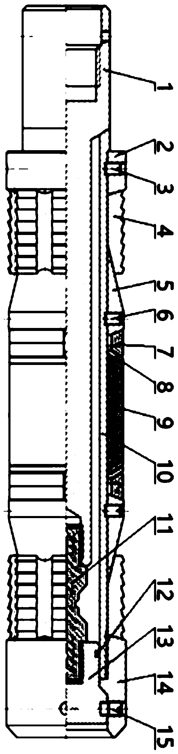
[0036] according to Figure 1-6 A large-diameter treatment-free downhole high-pressure temporary plugging tool is shown, including a hand-removing mechanism, a card sealing mechanism, a temporary plug 13, a support seat 14 and a fixing member; the lower end of the hands-free mechanism is detachably connected to the inner wall of the temporary plug 13 , the outer side wall of the upper part of the hand-losing mechanism is in contact with the upper end surface of the card sealing mechanism; the support seat 14 is sleeved on the outer side wall of the lower end of the temporary block 13 and fixed by a fixing member; the card sealing mechanism is arranged on the outer periphery of the hand-losing mechanism, and the sealing The lower end of the card mechanism is connected in the gap between the top of the support base 14 and the temporary plug 13 and is sealed with the temporary plug 13 by a seal.

[0037] It is preferable that the described fixing member adopts the starting shear ...

Embodiment 2

[0042] according to Figure 1-3 , Image 6 The large-diameter treatment-free downhole high-pressure temporary plugging tool shown is different from the first embodiment in that: the release mechanism includes a release rod 1 and a stress rod 11; the release rod 1 and the stress rod 11 is arranged up and down, and the outer side walls of the upper and lower ends of the stress rod 11 are respectively connected with the inner side walls of the throwing bar 1 and the temporary blockage 13 with screws.

[0043] Further, the stress rod 11 is a columnar body with an annular groove 19 for breaking in the middle.

[0044] In actual use, when the sealing mechanism moves downward under the thrust of the seat sealing tool, it completes contact with the inner wall of the casing 16, clamps, and squeezes the seal. The weak point provided in the middle part, that is, the annular groove 19, is broken, and the tool is completely lost.

[0045] In a specific application, the stress rod 11 ado...

Embodiment 3

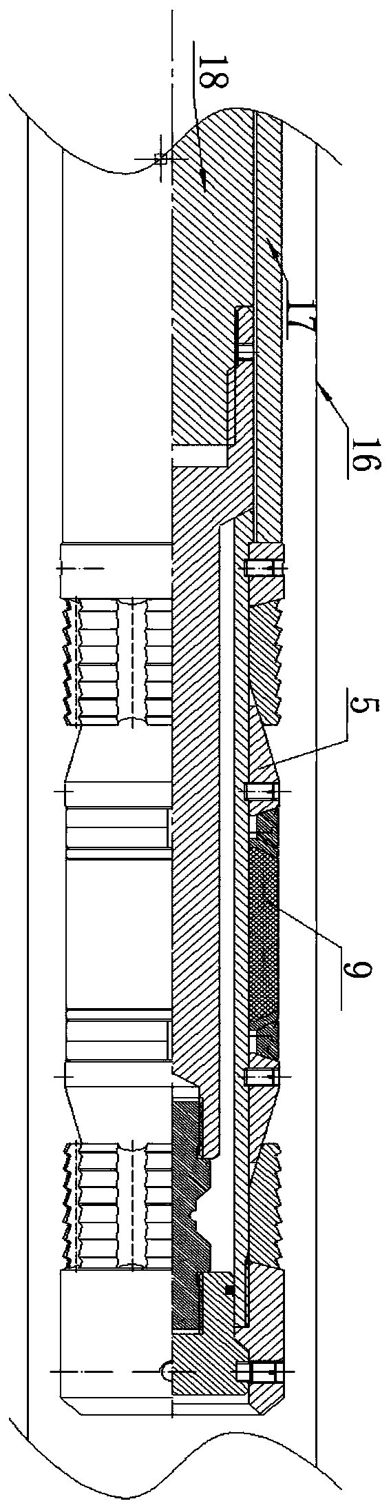
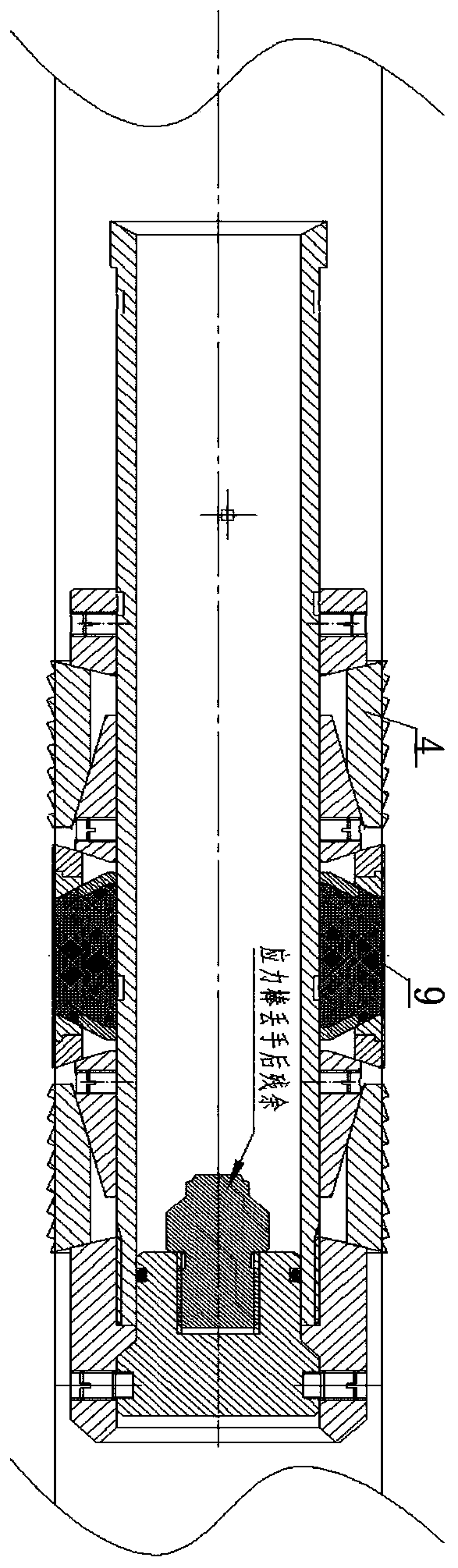
[0049] according to Figure 1-5 The large-diameter treatment-free downhole high-pressure temporary plugging tool shown is different from the first embodiment in that the sealing mechanism includes a movable sleeve 2, slips 4, a cone 5, and a second anti-seat shear nail 6 , protective umbrella 7, protective ring 8, rubber tube 9 and central tube 10; Outside; the rubber tube 9 is socketed in the middle of the central tube 10, and the retaining ring 8, the umbrella 7, the cone 5 and the slips 4 are arranged symmetrically on both sides with the rubber tube 9 as the center; the cone 5 The second anti-seat shear nail 6 is fixed to the central tube 10; the movable sleeve 2 is in contact with the upper slip 4, and is fixed to the central tube 10 by the first anti-seat shear nail 3; the upper end of the central tube 10 is connected to When the hands-off mechanism contacts, the lower end of the central tube 10 is connected in the gap between the support seat 14 top and the temporary bl...


PUM

PropertyMeasurementUnit
Diameteraaaaaaaaaa

Abstract

The invention belongs to the technical field of oil and gas field downhole technical operation tools, and particularly relates to a large-drift-diameter treatment-free downhole high-pressure temporaryplugging tool and method. The large-drift-diameter treatment-free downhole high-pressure temporary plugging tool is formed by organically combining a releasing mechanism, a sealing and clamping mechanism, a temporary plug, a supporting seat and a fixing piece. According to the large-drift-diameter treatment-free downhole high-pressure temporary plugging tool and method, through the penetrating type releasing structure, simpleness and reliability are achieved, the overall size of the tool is small, and the characteristic that the releasing load is adjustable due to the fact that the size of the releasing structure is changed is fully utilized; the main load is borne through the bottom supporting seat, stress of a center pipe is avoided, and the material performance limitation is broken through; and the center pipe has the large drift diameter with the pipe diameter being larger than or equal to 50mm and can be consistent with the inner diameter of a production oil pipe, later-period liquid discharging and oil pipe passing operation are smoothly conducted, and the construction safety is guaranteed. A cone, a protective umbrella, a protective ring and a rubber cylinder in the large-drift-diameter treatment-free downhole high-pressure temporary plugging tool all adopt self-releasing materials, failure can be automatically released after construction is finished, and the full driftdiameter of a shaft can be achieved without special treatment subsequently.

Description

technical field [0001] The invention belongs to the technical field of oil and gas field reservoir transformation, and in particular relates to a large-diameter treatment-free downhole high-pressure temporary plugging device and method. Background technique [0002] In the development of oil and gas fields in the prior art, in order to achieve rapid production after the completion of coiled tubing fracturing of oil and gas wells, it is often necessary to cooperate with the production string with pressurized equipment. However, the snubbing operation is technically difficult and has high construction risks. Using snubbing equipment to cooperate with the production string often causes other high-risk wells to stop waiting, which is not conducive to the rapid development of oil and gas resources. At present, in response to this situation, there have been two downhole temporary plugging schemes based on traditional bridge plugs. One is a fishable bridge plug with internal tempor...

Claims


Application Information

Patent Timeline
IPC IPC(8): E21B33/129E21B33/127
CPCE21B33/127E21B33/129
Inventor 牛朋伟张文苏敏文费节高邓小强廖作杰陈世波许建伟高宇田文超庞磊晏健王伟鹏韩硕王旭
Owner BC P INC CHINA NAT PETROLEUM CORP
Why Eureka
Try Eureka