
Semiconductor strain balance applied to pulse wind tunnel

A technology of strain balances and semiconductors, which is used in the testing, measuring devices, instruments, etc. of machine/structural components, which can solve the problem that the stiffness of the strain balance cannot be satisfied, the frequency response cannot be satisfied, the strain design of the strain balance cannot be too small, and the sensitivity coefficient of the resistance strain gauge is low. and other problems, to achieve the effect of improving sensitivity and measurement accuracy, enhancing stiffness, and high sensitivity

Pending Publication Date: 2020-06-05
中国空气动力研究与发展中心超高速空气动力研究所
View PDF0 Cites 6 Cited by
  • Summary
  • Abstract
  • Description
  • Claims
  • Application Information

AI Technical Summary

Problems solved by technology

[0003] Conventional strain balances have advantages in terms of structural decoupling and performance stability. However, since the sensitivity coefficient of resistance strain gauges is very low, only about 2, the strain design of strain balances should not be too small under the premise of ensuring sufficient signal output. Therefore, the stiffness and frequency response of the strain balance cannot meet the requirements of the pulsed wind tunnel with a test time of only a few to tens of milliseconds
The sensitivity coefficient of the piezoelectric sheet is relatively high, and the stiffness and frequency response of the piezoelectric balance can meet the requirements of a pulsed wind tunnel with a test time of only a few to tens of milliseconds. However, the stability of the piezoelectric sheet over time is poor, and its performance varies with The change of time has certain fluctuations, and the calibration of the piezoelectric balance is required for each wind tunnel force test, which is not conducive to the improvement of test efficiency

Method used


Image

  • Semiconductor strain balance applied to pulse wind tunnel
  • Semiconductor strain balance applied to pulse wind tunnel
  • Semiconductor strain balance applied to pulse wind tunnel

Examples


Embodiment 1

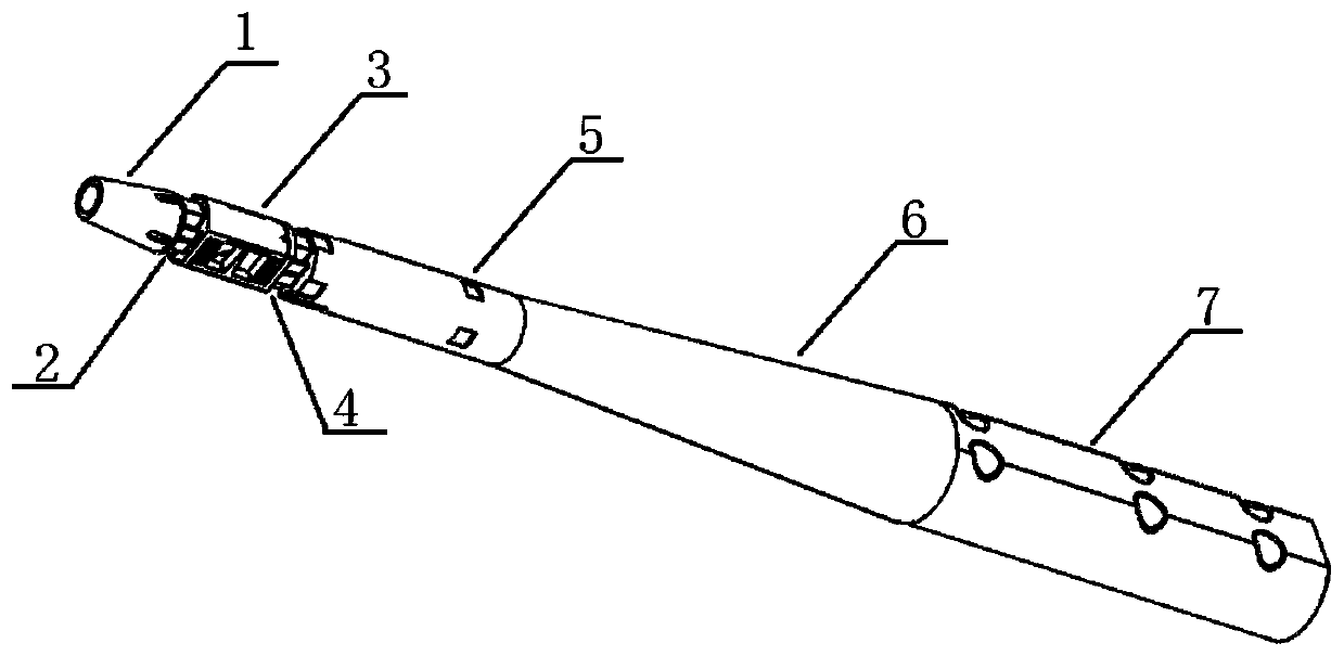
[0033] Such as figure 1 As shown, the semiconductor strain balance applied to the pulse wind tunnel of the present invention includes a model connecting section 1, a first combined measuring element 2, an axial force measuring element 3, a second combined measuring element 4, and an accelerometer mounting section from front to back 5. Balance pole 6 and support section 7;

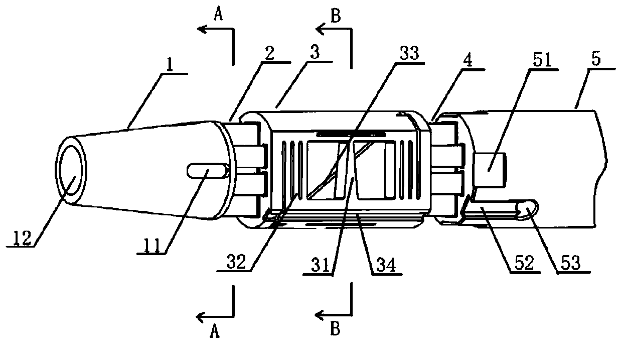
[0034] Such as figure 2 As shown, the model connection section 1 is a cone section that expands from front to back, and is connected with the wind tunnel test model through the cone surface. The keyway 11 is provided on the cone surface, which is used for the installation and positioning of the wind tunnel test model, and the model connection The front end of section 1 is provided with a threaded hole 12, which is used for compacting the wind tunnel test model;

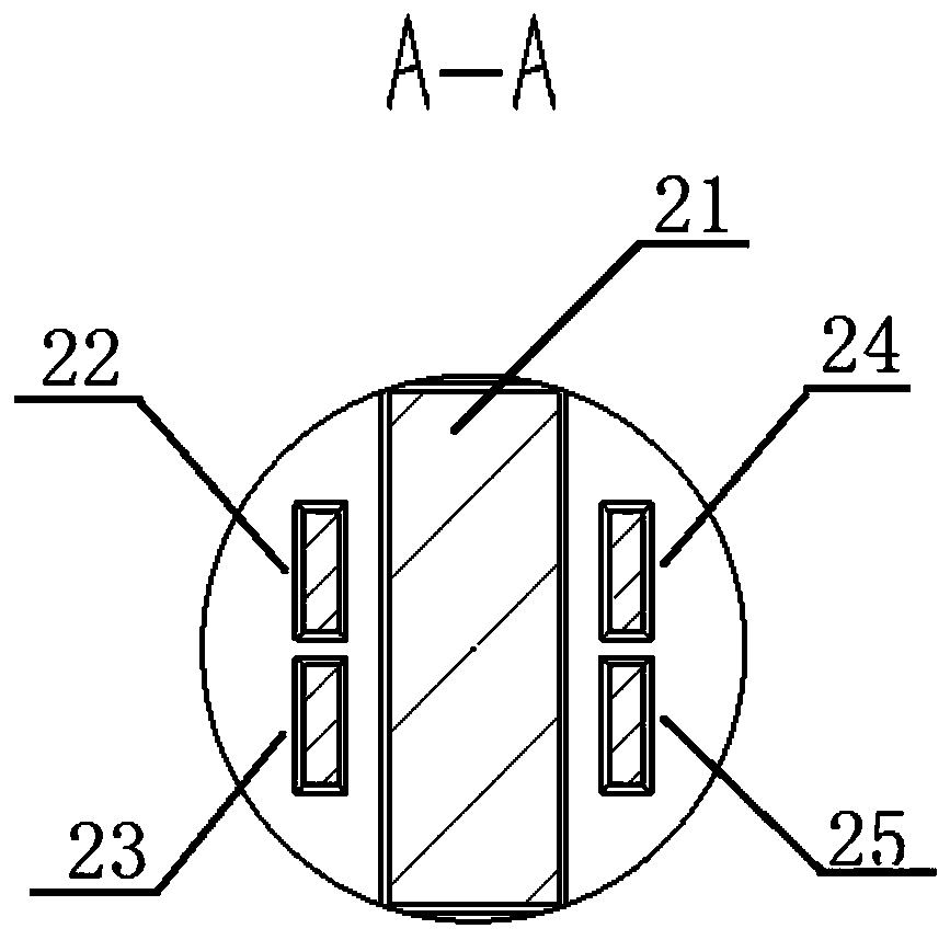
[0035] Such as figure 2 , 3 As shown, the first combined measuring element 2 is a five-piece beam structure, and the five-piece beam structu...


PUM


Abstract

The invention discloses a semiconductor strain balance applied to a pulse wind tunnel. The balance sequentially comprises a model connecting section, a first combined measuring element, an axial forcemeasuring element, a second combined measuring element, an accelerometer mounting section, a balance supporting rod and a supporting section from front to back. Aiming at the characteristic of shorteffective time of a pulse wind tunnel, the balance adopts a semiconductor strain balance form, and meanwhile, the balance and the supporting rod are designed into a whole, so that middle parts are reduced, and the rigidity of the balance is enhanced. According to the balance, on the basis of a three-piece beam type combined measuring element, a side piece beam is divided into an upper piece beam and a lower piece beam which are respectively used for measuring a lateral force, a yawing moment and a rolling moment, so that the sensitivity and the measuring precision of the rolling moment are improved.

Description

technical field [0001] The invention belongs to the field of wind tunnel equipment, and in particular relates to a semiconductor strain balance applied to a pulse wind tunnel. Background technique [0002] With the rapid development of various types of aircraft and weapons, wind tunnel dynamometric tests have higher and higher requirements for the measurement accuracy of small aerodynamic loads such as small lateral aerodynamic forces and small rolling moments of aircraft and weapons. The components have ideal decoupling. At the same time, for the pulse wind tunnel with a test time of only a few to tens of milliseconds, due to the short test time, the balance is also required to have a high frequency response. [0003] Conventional strain balances have advantages in terms of structural decoupling and performance stability. However, since the sensitivity coefficient of resistance strain gauges is very low, only about 2, the strain design of strain balances should not be too s...

Claims


Application Information

Patent Timeline
Patent Type & Authority Applications(China)
IPC IPC(8): G01M9/06
CPCG01M9/062
Inventor 黄军杨彦广邱华诚赵荣娟刘施然吕治国
Owner 中国空气动力研究与发展中心超高速空气动力研究所
Learn More