Compartment space occupancy detection method, device, system and storage medium
A technology of space occupation and detection method, applied in the field of detection and identification, can solve the problems of incompatibility and inconvenience of different vehicles
- Summary
- Abstract
- Description
- Claims
- Application Information
AI Technical Summary
Problems solved by technology
Method used
Image
Examples
no. 1 example
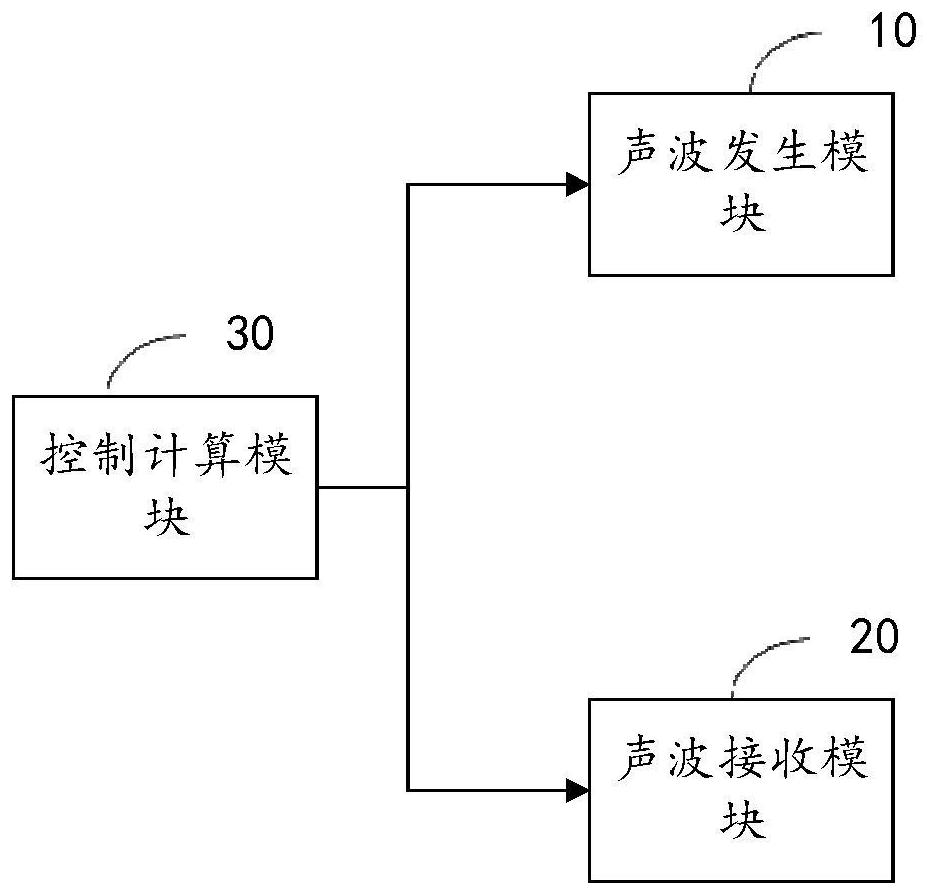
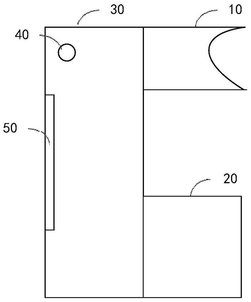
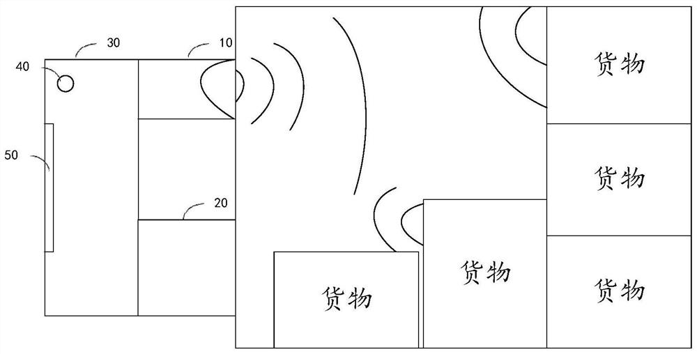
[0036] like figure 1 As shown, the embodiment of the present application provides a vehicle space occupancy detection system, the system includes an acoustic wave generating module 10, an acoustic wave receiving module 20 and a control calculation module 30, the acoustic wave generating module 10 and the acoustic wave receiving module 20 and the The control computing module 30 is electrically connected, the sound wave generating module 10 is used for transmitting the sound wave signal, and the sound wave receiving module 20 is used for receiving the sound wave signal returned by the sound wave signal transmitted by the sound wave generating module 10 after passing through the carriage, which can be called an echo signal. The control calculation module 30 is used to control the sound wave generating module to transmit a transmission signal of a preset time length to the vehicle under test, and calculate the duration of the echo signal received by the sound wave receiving module;...
no. 2 example
[0041] like Figure 4 As shown, the present application provides a method for detecting a compartment space occupancy rate, which can be applied to the control computing module described in the first embodiment, and the method specifically includes the following steps:
[0042] Step S200 : controlling the sound wave generating module to transmit a transmission signal of a preset time length to the vehicle under test.
[0043] Step S202 : calculating the duration of the echo signal received by the acoustic wave receiving module, where the echo signal is the acoustic wave signal reflected back by the transmitted signal through the carriage.
[0044] Step S204: Determine the space occupancy rate of the vehicle under test according to the preset time length of the transmitted signal and the duration of the echo signal.
[0045] In step S200, the above-mentioned sound wave generating module is a module capable of generating sound wave signals and transmitting, and the preset time ...
no. 3 example
[0073] Figure 9 A schematic structural block diagram of the vehicle space occupancy rate detection device provided by the present application is shown, and it should be understood that the device is similar to the above-mentioned Figure 4 to Figure 8 Corresponding to the method embodiment executed in the second embodiment, the steps involved in the method executed in the second embodiment can be executed. For the specific functions of the apparatus, refer to the above description. To avoid repetition, the detailed description is appropriately omitted here. The device includes at least one software function module that can be stored in a memory in the form of software or firmware or fixed in an operating system (OS) of the device. Specifically, the device includes: a control module 300 for controlling the sound wave generating module to transmit a transmission signal of a preset time length to the vehicle under test; a calculation module 302 for calculating the duration of th...
PUM
 Abstract
Description
Claims
Application Information
 - R&D
- Intellectual Property
- Life Sciences
- Materials
- Tech Scout
- Unparalleled Data Quality
- Higher Quality Content
- 60% Fewer Hallucinations
Browse by: Latest US Patents, China's latest patents, Technical Efficacy Thesaurus, Application Domain, Technology Topic, Popular Technical Reports.
© 2025 PatSnap. All rights reserved.Legal|Privacy policy|Modern Slavery Act Transparency Statement|Sitemap|About US| Contact US: help@patsnap.com


