Optical system, lens module and terminal equipment

An optical system and lens technology, applied in optics, optical components, instruments, etc., can solve the problem that the overall pixel is difficult to be guaranteed, and achieve the effect of being conducive to long-distance observation, correcting aberrations, and improving resolution capabilities.

Pending Publication Date: 2020-06-05
JIANGXI JINGCHAO OPTICAL CO LTD
View PDF0 Cites 5 Cited by
  • Summary
  • Abstract
  • Description
  • Claims
  • Application Information

AI Technical Summary

Problems solved by technology

Due to the characteristics of long-distance shooting, the existing front-view camera needs to have a long focal length, but the overall pixel is difficult to guarantee

Method used


Image

  • Optical system, lens module and terminal equipment
  • Optical system, lens module and terminal equipment
  • Optical system, lens module and terminal equipment

Examples


Embodiment 1

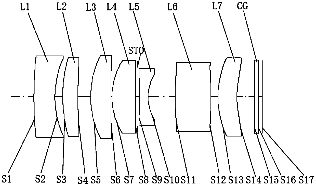
[0071] Such as figure 2 As shown, the straight line in the middle indicates the optical axis, the left side of the optical system is the object side, and the right side is the image side. In the optical system provided by this embodiment, from the object side to the image side, there are first lens L1, second lens L2, third lens L3, fourth lens L4, diaphragm STO, fifth lens L5, and sixth lens L6, seventh lens L7, and cover glass CG.

[0072] The first lens L1 has negative refractive power and is made of glass. The object-side surface S1 is convex, and the image-side surface S2 is concave, both of which are spherical.

[0073] The second lens L2 has a positive refractive power and is made of glass. The object-side surface S3 is convex, and the image-side surface S4 is concave, both of which are spherical.

[0074] The third lens L3 has a positive refractive power and is made of glass. The object-side surface S5 is convex, and the image-side surface S6 is a plane, both of whi...

Embodiment 2

[0095] Such as Figure 6 As shown, the straight line in the middle indicates the optical axis, the left side of the optical system is the object side, and the right side is the image side. In the optical system provided by this embodiment, from the object side to the image side, there are first lens L1, second lens L2, third lens L3, fourth lens L4, diaphragm STO, fifth lens L5, and sixth lens L6, seventh lens L7, and cover glass CG.

[0096] The first lens L1 has a negative refractive power and is made of glass. The object-side surface S1 is concave, and the image-side surface S2 is concave, both of which are spherical.

[0097] The second lens L2 has a positive refractive power and is made of glass. The object-side surface S3 is convex, and the image-side surface S4 is convex, both of which are spherical.

[0098] The third lens L3 has a positive refractive power and is made of glass. The object-side surface S5 is convex, and the image-side surface S6 is concave, both of w...

Embodiment 3

[0118] Such as Figure 10 As shown, the straight line in the middle indicates the optical axis, the left side of the optical system is the object side, and the right side is the image side. In the optical system provided by this embodiment, from the object side to the image side, there are first lens L1, second lens L2, third lens L3, fourth lens L4, diaphragm STO, fifth lens L5, and sixth lens L6, seventh lens L7, and cover glass CG.

[0119] The first lens L1 has a negative refractive power and is made of glass. The object-side surface S1 is concave, and the image-side surface S2 is concave, both of which are spherical.

[0120] The second lens L2 has a positive refractive power and is made of glass. The object-side surface S3 is convex, and the image-side surface S4 is convex, both of which are spherical.

[0121] The third lens L3 has a positive refractive power and is made of glass. The object-side surface S5 is convex, and the image-side surface S6 is concave, both of ...


PUM


Abstract

The embodiment of the invention discloses an optical system, a lens module and terminal equipment. The optical system comprises a first lens, a second lens, a third lens, a fourth lens, a fifth lens,a sixth lens and a seventh lens which are sequentially arranged from the object side to the image side, wherein the first lens and the fifth lens have negative refractive power, the other lenses havepositive refractive power, and the optical system satisfies the following conditional expressions: 40 < (HFOV * f)/Imgh < 60, wherein HFOV is the field angle of the optical system in the horizontal direction, f is the effective focal length of the optical system, and Imgh is the image height corresponding to the field angle of the optical system in the horizontal direction. Through reasonable configuration of refractive power of the first lens to the seventh lens in the optical system and limitation of (HFOV * f)/Imgh, the optical system is enabled to meet the characteristics of long focal length and high pixel, a long-distance object can be clearly shot, the image quality is better, and the image has more details.

Description

technical field [0001] The invention belongs to the technical field of optical imaging, and in particular relates to an optical system, a lens module and terminal equipment. Background technique [0002] With the continuous development of automobile technology (such as assisted driving technology, automatic driving and unmanned driving) and the improvement of people's requirements for car driving safety, the application of car cameras is becoming more and more popular and favored by more people. Functionality varies depending on where it is installed. [0003] The front-view camera needs to observe images from a longer distance and bring distant objects closer, so that the on-board system can monitor the road conditions ahead in real time and provide guarantee for safe driving. Due to the characteristics of long-distance shooting, the existing front-view camera needs to have a long focal length, but it is difficult to guarantee the overall pixel. [0004] How to make the f...

Claims


Application Information

Patent Timeline
Patent Type & Authority Applications(China)
IPC IPC(8): G02B13/00G02B13/18
CPCG02B13/0045G02B13/18
Inventor 蔡雄宇兰宾利周芮赵迪
Owner JIANGXI JINGCHAO OPTICAL CO LTD
Why Eureka
Try Eureka