Winding displacement structure of capacitor motor stator winding and working method thereof

A technology of motor stator and wire structure, applied in the shape/style/structure of winding conductors, electric components, magnetic circuit shape/style/structure, etc., can solve the problems of insufficient phase winding, small torque, low efficiency, etc., and achieve saving The effect of electrical energy, increased work efficiency and torque

Pending Publication Date: 2020-06-05
陈伯川
View PDF0 Cites 3 Cited by
  • Summary
  • Abstract
  • Description
  • Claims
  • Application Information

AI Technical Summary

Problems solved by technology

[0004] Aiming at the above-mentioned deficiencies in the prior art, the technical problem to be solved by the present invention is: how to provide a design scheme for the wiring structure of the stator winding of a capacitor motor, and a working method of the stator winding of a capacitor motor, so as to solve the problem of existing capacitors. Problems such as low efficiency and low torque caused by insufficient phase windings in the motor

Method used


Image

  • Winding displacement structure of capacitor motor stator winding and working method thereof
  • Winding displacement structure of capacitor motor stator winding and working method thereof
  • Winding displacement structure of capacitor motor stator winding and working method thereof

Examples


Embodiment Construction

[0030] The present invention will be further described below in conjunction with the accompanying drawings and embodiments.

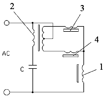
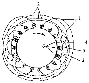
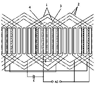
[0031] as attached figure 1 to attach image 3 As shown, a wire arrangement structure of the stator winding of a capacitor motor includes a main winding 1 and an auxiliary winding 2 embedded in the stator slot. The main winding 1 and the auxiliary winding 2 are separated by a phase angle of 90°. It is a concentric distributed winding, and also includes a shunt winding. The shunt winding is distributed in the stator slot inside the corresponding position of the main winding 1. The shunt winding includes the first shunt winding 3 and the second shunt winding 4. The first shunt winding 3 refers to the auxiliary winding 2 The electrode phase of the first shunt winding 3 is shifted to the left by a set angle, the right side of the electrode of the first shunt winding 3 is overlapped on the right side of the electrode of the secondary winding 2, and the left...


PUM


Abstract

The invention discloses a winding displacement structure of a capacitor motor stator winding and a working method thereof. The winding displacement structure comprises a main winding, an auxiliary winding and a shunt winding. The shunt windings comprise a first shunt winding and a second shunt winding; the first shunt winding deviates leftwards by a set angle by referring to the electrode phase ofthe auxiliary winding; the electrode right side is overlapped on the electrode right side of the auxiliary winding; the left side is distributed in the junction area of the electrode left side of theauxiliary winding and the main winding; the second shunt winding deviates rightwards by a set angle according to the electrode phase of the auxiliary winding, and the left side of the electrode is overlapped on the left side of the electrode of the auxiliary winding; the right side of the electrode of the second shunt winding is distributed in the junction area of the right side of the electrodeof the auxiliary winding and the main winding; and the first shunt winding and the second shunt winding are connected in parallel in the winding direction and then connected with the main winding in series. According to the invention, a positioning excitation mode of the main winding is changed into a stepping excitation mode; the power supply problem of a secondary-phase dummy power supply is solved; and the working efficiency and the torque of the capacitor motor are improved.

Description

technical field [0001] The invention relates to the technical field of electric motors, in particular to a wire arrangement structure of a stator winding of a capacitor electric motor and a working method thereof. Background technique [0002] In the prior art, the wiring of the capacitor motor is completely referred to the "phase winding positioning" wiring method of the three-phase motor, and the phase windings of the positioning excitation need at least three phase windings to turn around during the stepping and alternating operation; There are only two sets of phase windings for the capacitor motor to rotate, which are the main winding and the secondary winding embedded in the stator slots with a phase distance of 90°, and the stator core of the capacitor motor is provided with multiple stator slots. The two ends of the two ends and the two ends of the auxiliary winding are distributed in different stator slots. When working, the single-phase power supply uses a capacito...

Claims


Application Information

Patent Timeline
Patent Type & Authority Applications(China)
IPC IPC(8): H02K3/16H02K3/28H02K1/16
CPCH02K1/165H02K3/16H02K3/28H02K2213/03
Inventor 陈伯川饶鹏
Owner 陈伯川
Why Eureka
Try Eureka