
Centrifugal grinding system

A centrifugal and centrifugal separator technology, which is applied in the field of ball milling and crushing, can solve the problems of affecting the use and order, not easy to balance the dynamic balance of the separator, and affecting the separation efficiency.

Pending Publication Date: 2020-06-09
HUBEI MAIZHAO MASCH CO LTD
View PDF9 Cites 1 Cited by
  • Summary
  • Abstract
  • Description
  • Claims
  • Application Information

AI Technical Summary

Problems solved by technology

Although the above structure partly solves the problem that the grinding balls are discharged through the separation hole, it is difficult to process due to the complicated structure of the separator.
At the same time, it is not easy to control the dynamic balance of the separator during high-speed rotation, which affects the use and order; at the same time, the separation path of the separation hole of the spiral structure is long, which is easy to block the separation hole and affect the separation efficiency.

Method used


Image

  • Centrifugal grinding system
  • Centrifugal grinding system
  • Centrifugal grinding system

Examples


Embodiment Construction

[0029] The claims of the present invention will be further described in detail below in conjunction with specific embodiments and drawings. Obviously, the described embodiments are only part of the embodiments of the present invention. Based on the embodiments of the present invention, all other embodiments obtained by persons of ordinary skill in the art without making creative work belong to the protection scope of the present invention.

[0030] It should be understood that, in the description of the present invention, all directional terms, such as "up", "down", etc. indicate the orientation or positional relationship based on the orientation or positional relationship shown in the drawings or are used by the product of the invention. The orientations or positional relationships that are conventionally placed are only for the convenience of describing the present invention and simplifying the description, and do not indicate or imply that the referred device or element must...


PUM


Abstract

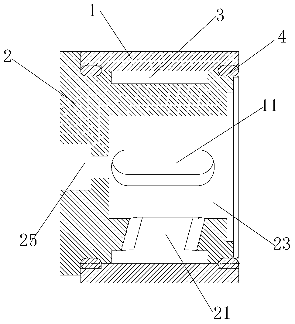
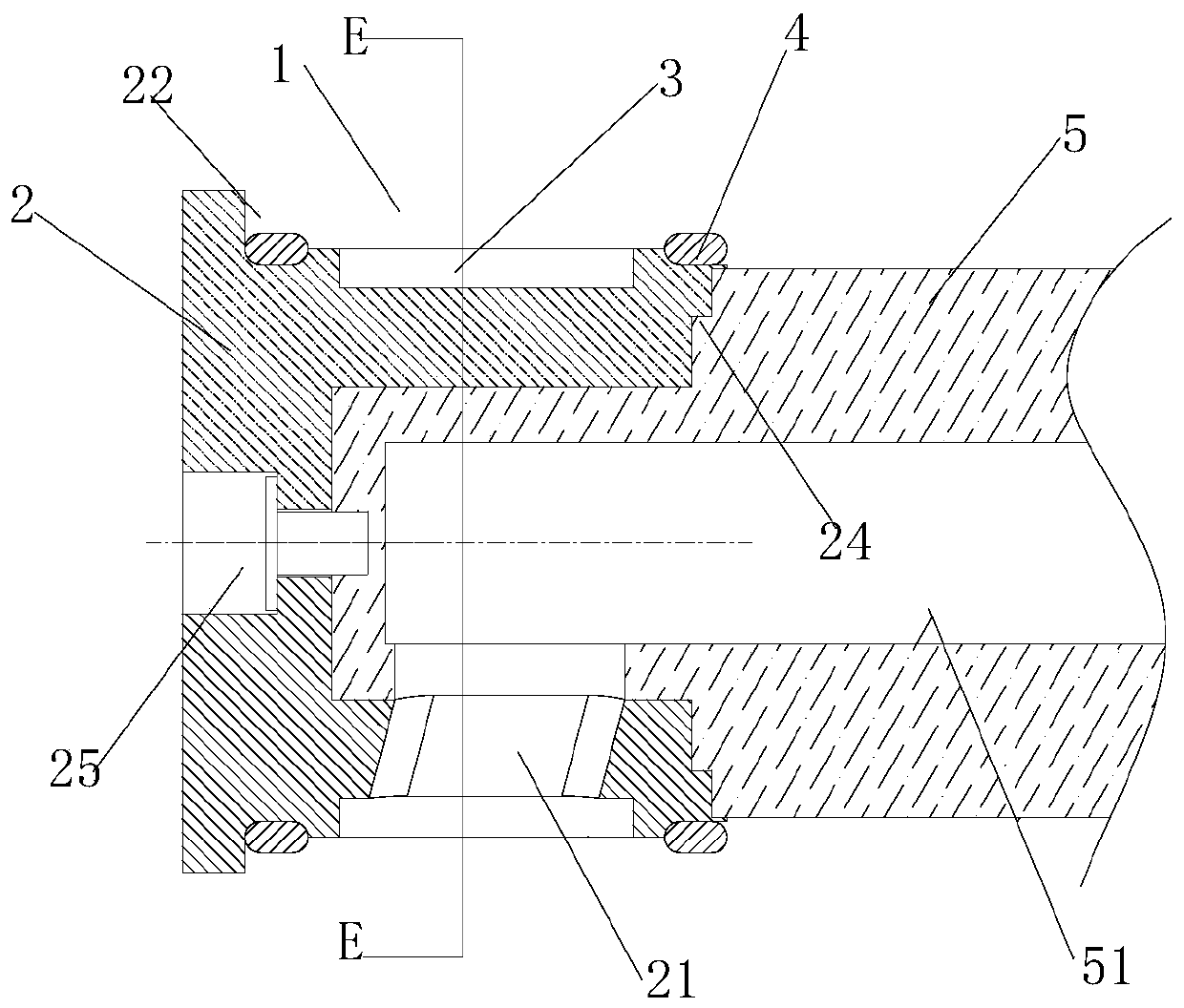
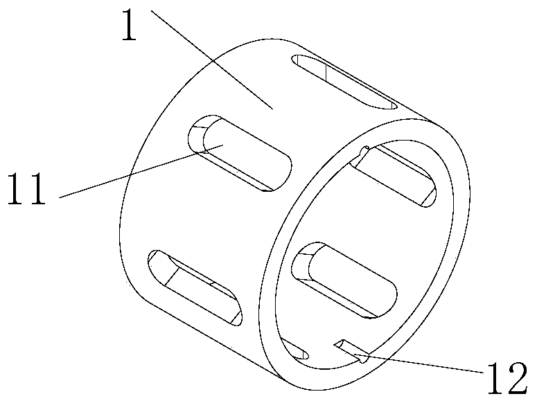
The invention belongs to the technical field of ball mill pulverization. The invention discloses a centrifugal grinding system which includes a grinding cylinder, a centrifugal separator, and a driving mechanism for driving the centrifugal separator to work. The centrifugal separator includes a separation outer sleeve and a separation inner cylinder arranged in the separation outer sleeve. The separation inner cylinder is provided with an inner cylinder separation hole, the separation outer sleeve is provided with an outer sleeve compound hole which provides energy to enables a grinding mediumto move outwards and classify a material during rotating, a separation cavity closed in axial direction is formed between the separation inner cylinder and the separation outer sleeve, and the separation cavity communicates with the outer sleeve compound hole and the inner cylinder separation hole correspondingly. During use, the separator rotates under the drive of a separation drive shaft, theouter sleeve compound hole can provide power for the grinding medium and the larger diameter material to be away from the separation outer sleeve, and can provide a channel for the smaller diameter material to enter the separation cavity for classification. The material enters into the separation cavity in stages easily, and the material is discharged through the inner cylinder separation hole, sothat the separation efficiency is improved.

Description

technical field [0001] The invention relates to the technical field of ball milling, in particular to a centrifugal grinding system. Background technique [0002] Existing wet ball milling equipment includes a grinding cylinder, an agitator or a disperser connected between the grinding cylinder and a rotating shaft, and a separator disposed on a material discharge hole in the grinding cylinder. The grinding balls added to the grinding cylinder during grinding are about 2 / 3 of the cavity of the grinding cylinder. When the centrifugal separator works, the disperser and separator connected to the main shaft rotate at high speed, and the grinding balls are distributed Because it is close to the inner wall of the grinding cylinder, there are fewer grinding balls distributed around the separator in the middle of the grinding cylinder. During separation, under the action of centrifugal force, only the ground materials will enter the discharge hole from the separation hole on the se...

Claims


Application Information

Patent Timeline
Patent Type & Authority Applications(China)
IPC IPC(8): B02C17/10B02C17/16B02C17/18B02C17/24
CPCB02C17/10B02C17/161B02C17/18B02C17/24
Inventor 占天义
Owner HUBEI MAIZHAO MASCH CO LTD
Learn More