
An easy-to-use photocatalyst spraying device
A spraying device and photocatalyst technology, which is applied in the field of photocatalyst, can solve the problems that affect the user's experience of using the spraying device, the mixing effect of photocatalyst coating is poor, and the photocatalyst coating is prone to solidification or precipitation, etc., so as to improve the user experience, good mixing function and structure simple effect
- Summary
- Abstract
- Description
- Claims
- Application Information
AI Technical Summary
Problems solved by technology
Method used
Image

Examples
Embodiment 1
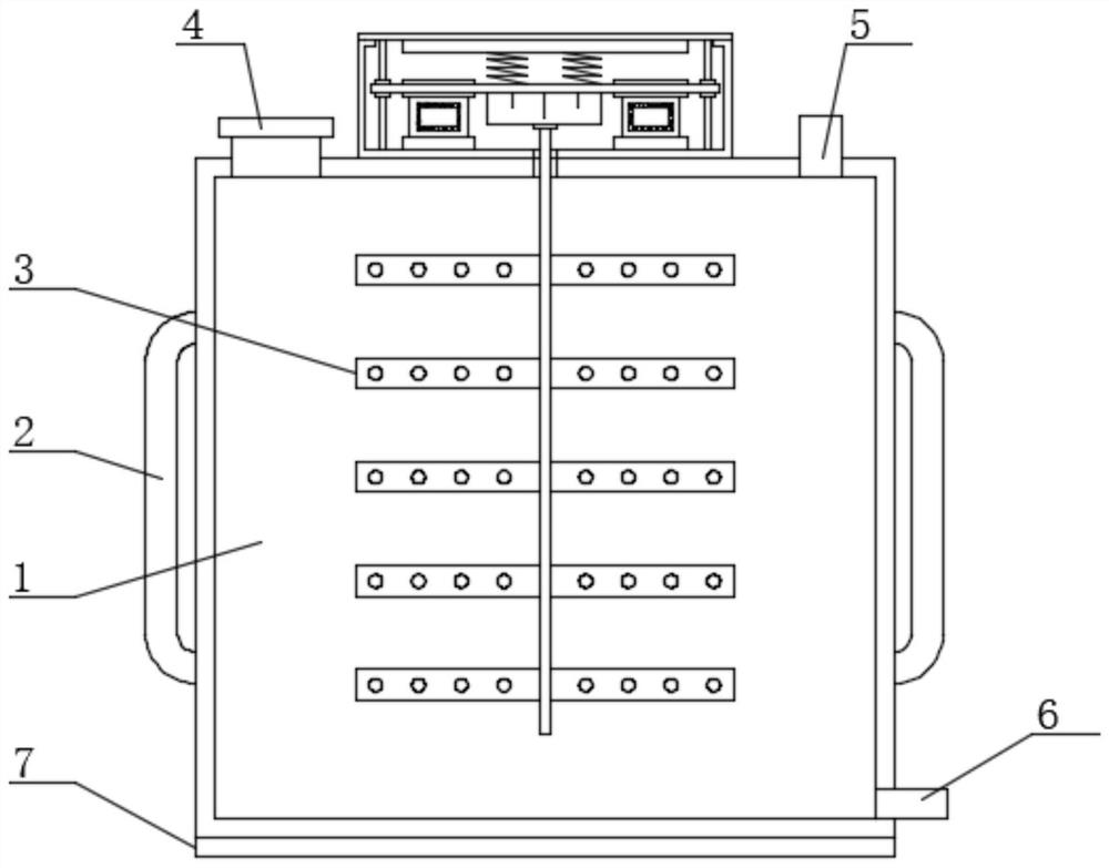
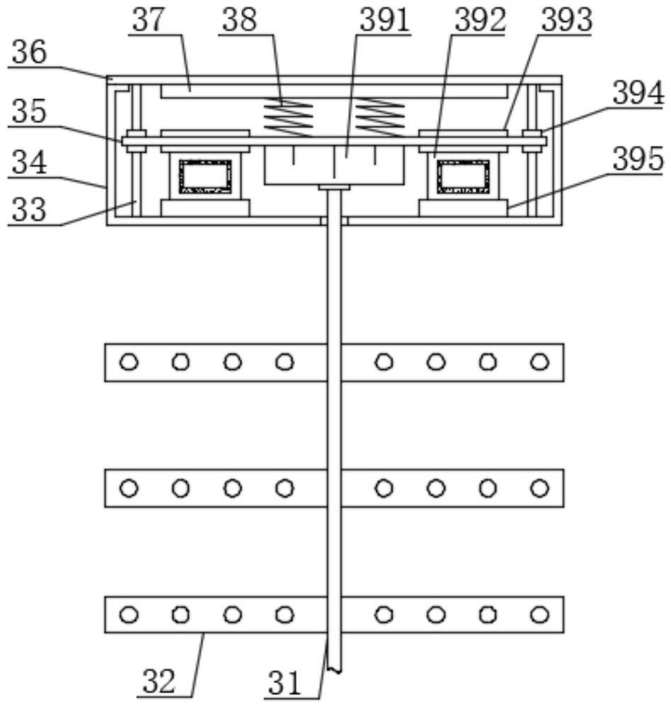
[0023] see Figure 1-Figure 3 , the present invention provides a technical solution: a photocatalyst spraying device that is easy to use, including a storage box 1, one end of the upper surface of the storage box 1 is provided with an integrally formed feed pipe 4, and the top of the feed pipe 4 is provided with Sealing cover, the other end of the upper surface of the material storage box 1 is provided with an integrally formed air intake pipe 5, the use of the material storage box 1 and the air intake pipe 5 is prior art, and one side of the material storage box 1 is provided with a back strap 2, and the back strap 2 The material is nylon, and the use of straps 2 is prior art. The bottom end of the material storage box 1 is provided with an integrally formed discharge pipe 6, and the middle part of the upper surface of the material storage box 1 is provided with a stirring mechanism 3;
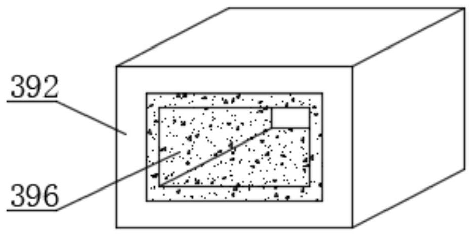
[0024] Stirring mechanism 3 comprises position-limiting base 34, and the top of position-...
Embodiment 2
[0033] On the basis of Embodiment 1, in order to make the limiting effect of the limiting rod 33 better, in this embodiment, preferably, the limiting rod 33 is a cylindrical structure, and the bottom end of the limiting rod 33 and the limiting base 34 Fixedly connected by welding, in order to make the disassembly and assembly of the protective cover 36 more convenient, in this embodiment, preferably, the protective cover 36 and the limit base 34 are fixedly connected by bolts;
[0034] In order to make the limiting effect of the limiting sleeve 394 on the limiting rod 33 better, in this embodiment, preferably, the limiting sleeve 394 is a hollow cylindrical structure, and the limiting sleeve 394 is set through the support plate 35, The limit sleeve 394 is fixedly connected to the support plate 35 by welding;
[0035] In order to make the anti-slip effect of the material storage box 1 better, in the present embodiment, preferably, the lower surface of the material storage box 1...
PUM
 Abstract
Description
Claims
Application Information