
Clamp for numerical control machining

A fixture and mounting plate technology, which is applied in the direction of manufacturing tools, metal processing equipment, metal processing machinery parts, etc., can solve the problems of lack of internal hole positioning and clamping devices that can meet the requirements, and achieve ingenious structural design, flexible and convenient use, and installation clip reliable effect

Active Publication Date: 2020-06-09
HUNAN MECHANICAL & ELECTRICAL POLYTECHNIC
View PDF6 Cites 5 Cited by
  • Summary
  • Abstract
  • Description
  • Claims
  • Application Information

AI Technical Summary

Problems solved by technology

[0002] When existing workpieces are numerically controlled, welded, drilled, etc., it is often necessary to position and clamp the inner hole of the workpiece to facilitate the rapid processing of the workpiece. However, there is no positioning and clamping device for the inner hole that can meet the requirements. Further research and development

Method used


Image

  • Clamp for numerical control machining
  • Clamp for numerical control machining
  • Clamp for numerical control machining

Examples


Embodiment Construction

[0022] In order to enable those skilled in the art to better understand the technical solution of the present invention, the present invention will be described in detail below in conjunction with the accompanying drawings. The description in this part is only exemplary and explanatory, and should not have any limiting effect on the protection scope of the present invention. .

[0023] It should be noted that like numerals and letters denote similar items in the following figures, therefore, once an item is defined in one figure, it does not require further definition and explanation in subsequent figures.

[0024] It should be noted that the orientation or positional relationship indicated by the terms "center", "upper", "lower", "left", "right", "vertical", "horizontal", "inner" and "outer" are Based on the orientation or positional relationship shown in the drawings, or the orientation or positional relationship that the inventive product is usually placed in use, it is onl...


PUM


Abstract

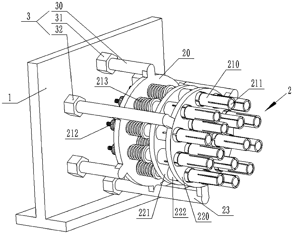
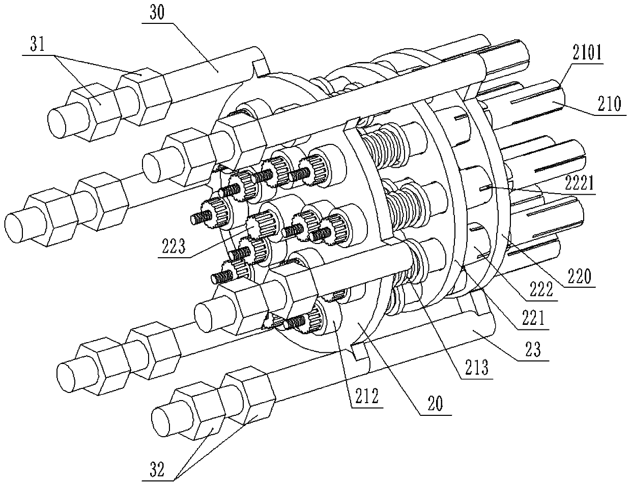
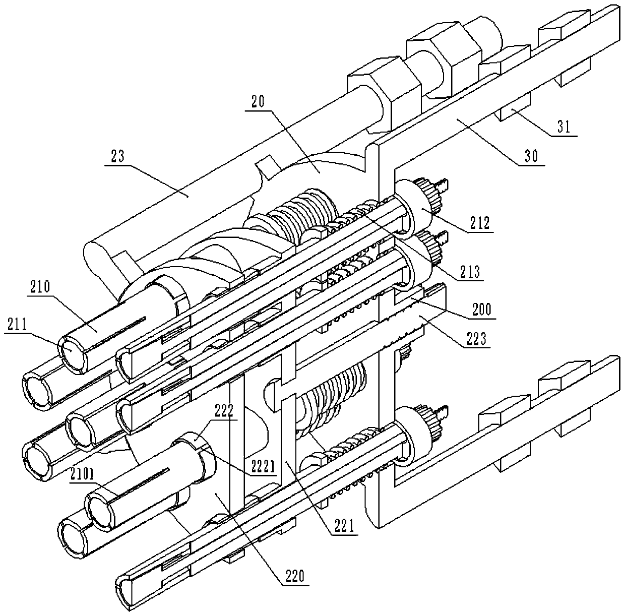
The invention discloses a clamp for numerical control machining. The clamp comprises a support and an inner hole positioning and expansion mechanism. The inner hole positioning and expansion mechanismcomprises an installing plate, an expansion assembly and a locking assembly. The expansion assembly comprises an expansion sleeve, a spindle and a locking nut. The locking assembly comprises a locking plate, locking sleeves screws and a positioning plate. The installing plate is connected with the support. A plurality of first positioning holes are circumferentially and evenly distributed in theinstalling plate. A plurality of through holes are circumferentially and evenly distributed in the positioning plate. Each through hole is aligned and connected with the corresponding locking sleeve.A plurality of second positioning holes are circumferentially and evenly distributed in the locking plate. The first positioning holes, the through holes and the second positioning holes are the samein number and corresponding in position. The clamp is ingenious in structural design, convenient to use and reliable in clamping.

Description

technical field [0001] The invention relates to the technical field of engineering machinery, in particular to a fixture for numerical control machining. Background technique [0002] When existing workpieces are numerically controlled, welded, drilled, etc., it is often necessary to position and clamp the inner hole of the workpiece to facilitate the rapid processing of the workpiece. However, there is no positioning and clamping device for the inner hole that can meet the requirements. further research and development. Contents of the invention [0003] The object of the present invention is to overcome the deficiencies of the prior art and provide a clamp for numerical control machining with ingenious structural design, convenient use and reliable clamping. [0004] In order to achieve the above object, the present invention provides a fixture for numerical control machining, including a bracket and an inner hole positioning expansion mechanism, the inner hole position...

Claims


Application Information

Patent Timeline
IPC IPC(8): B23Q3/06B23B31/40
CPCB23B31/4066B23Q3/061
Inventor 向东陈晖
Owner HUNAN MECHANICAL & ELECTRICAL POLYTECHNIC
Learn More