Anti-collision beam mounting plate, anti-collision beam assembly and vehicle

A technology of mounting plate and anti-collision beam, which is applied in the directions of vehicle components, transportation and packaging, substructure, etc., can solve the problems of poor connection stability between the anti-collision beam and the front-end frame, large vibration amplitude of the cooling module, affecting the working stability, etc. Achieve the effect of improving connection stability, enhancing its own structural strength, and improving heat dissipation performance

Inactive Publication Date: 2020-06-09
BORGWARD AUTOMOTIVE CHINA CO LTD
View PDF5 Cites 0 Cited by
  • Summary
  • Abstract
  • Description
  • Claims
  • Application Information

AI Technical Summary

Problems solved by technology

[0004] The main purpose of the present invention is to provide an anti-collision beam mounting plate, an anti-collision beam assembly and a vehicle, so as to solve the poor connection stability between the anti-collision beam and the front frame due to the unreasonable structure of the anti-collision beam mounting plate in the prior art , the vibration amplitude of the cooling module is too large, which affects its working stability

Method used


Image

  • Anti-collision beam mounting plate, anti-collision beam assembly and vehicle
  • Anti-collision beam mounting plate, anti-collision beam assembly and vehicle

Examples


Embodiment Construction

[0021] The following will clearly and completely describe the technical solutions in the embodiments of the present invention with reference to the accompanying drawings in the embodiments of the present invention. Obviously, the described embodiments are only some of the embodiments of the present invention, not all of them. The following description of at least one exemplary embodiment is merely illustrative in nature and in no way taken as limiting the invention, its application or uses. Based on the embodiments of the present invention, all other embodiments obtained by persons of ordinary skill in the art without creative efforts fall within the protection scope of the present invention.

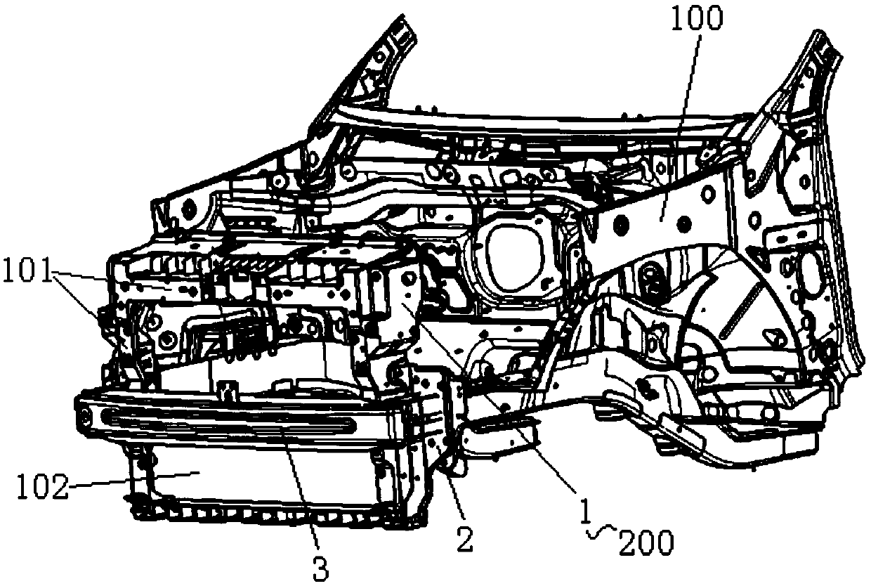
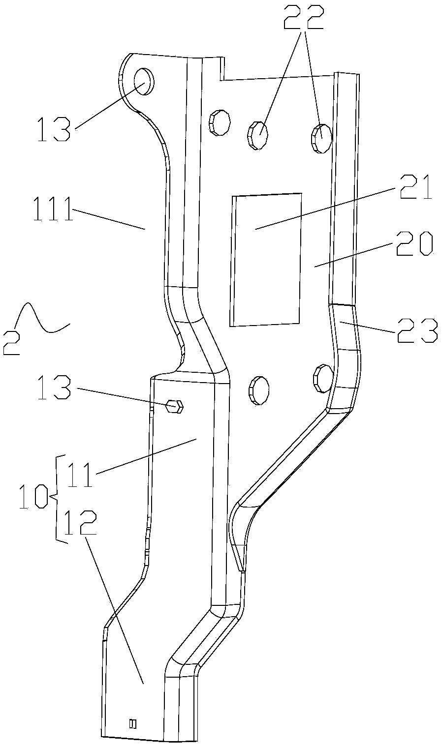
[0022] In order to solve the problem that the unreasonable structure of the anti-collision beam mounting plate in the prior art leads to poor connection stability between the anti-collision beam and the front-end frame, and makes the vibration amplitude of the cooling module too large to...


PUM


Abstract

The invention provides an anti-collision beam mounting plate, an anti-collision beam assembly and a vehicle. The anti-collision beam mounting plate is used for mounting an anti-collision beam on a front end frame. The anti-collision beam mounting plate comprises: a first mounting plate used for being connected with the front end frame; and a second mounting plate, wherein the second mounting plateis connected with the side edge of the first mounting plate, the second mounting plate and the first mounting plate are arranged in a bent mode, the second mounting plate is used for mounting and fixing the anti-collision beam, the first mounting plate comprises a connecting plate section and a reinforcing plate section in the length direction of the first mounting plate, and the reinforcing plate section is connected with the connecting plate section and located below the connecting plate section. The problems that an anti-collision beam mounting plate in the prior art is unreasonable in structure, so that the connecting stability of an anti-collision beam and a front end frame is poor, the vibration amplitude of a cooling module is too large, and the working stability of the cooling module is affected are solved.

Description

technical field [0001] The invention relates to the technical field of vehicle structures, in particular to an anti-collision beam mounting plate, an anti-collision beam assembly and a vehicle. Background technique [0002] In related technologies, the anti-collision beam of the vehicle is connected to the front-end frame of the vehicle through the anti-collision beam mounting plate, and in order to improve the compactness of the body structure of the vehicle, the front-end frame is also used to install a cooling device that can dissipate heat from the heated parts of the vehicle. Module, and in order to ensure that the cooling module has good NVH performance and ensure its heat dissipation effect; it is necessary to ensure that the cooling module works in a relatively stable environment. [0003] In the prior art, the structure of the anti-collision beam mounting plate is unreasonable, resulting in poor connection stability between the anti-collision beam and the front-end ...

Claims


Application Information

Patent Timeline
IPC IPC(8): B62D21/15
CPCB62D21/15
Inventor 王艳曾宪棣
Owner BORGWARD AUTOMOTIVE CHINA CO LTD
Why Eureka
Try Eureka