Lead screw braking device for vehicle automatic doors

A brake device and automatic door technology, which is applied in the field of rail transit, can solve problems such as reliability limitations, and achieve the effects of stable damping performance, easy adjustment, and simple braking structure

Pending Publication Date: 2020-06-09
IVY MACHINERY NANJING
View PDF1 Cites 3 Cited by
  • Summary
  • Abstract
  • Description
  • Claims
  • Application Information

AI Technical Summary

Problems solved by technology

However, optoelectronic components are also used in the aforementioned driving mechanism, which limits its reliability.

Method used


Image

  • Lead screw braking device for vehicle automatic doors
  • Lead screw braking device for vehicle automatic doors
  • Lead screw braking device for vehicle automatic doors

Examples


Embodiment 1

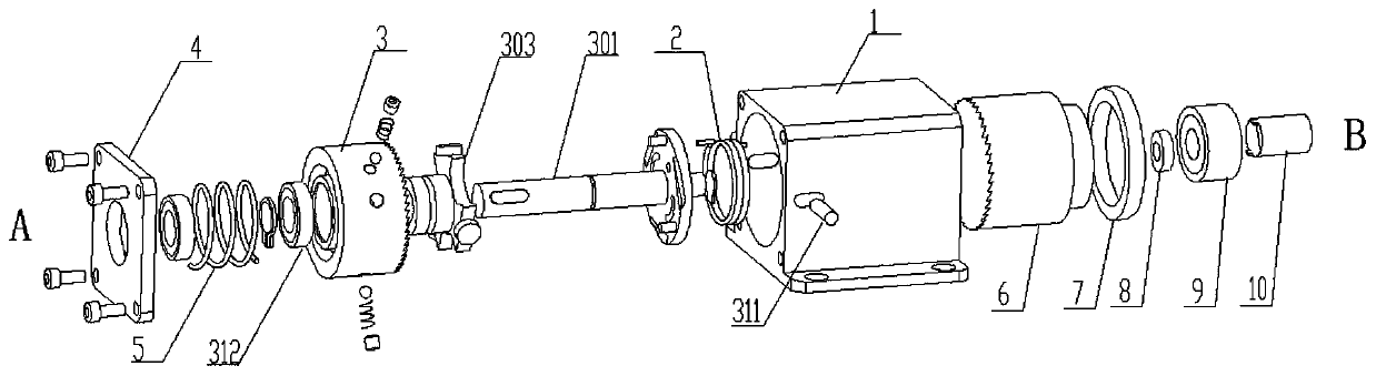
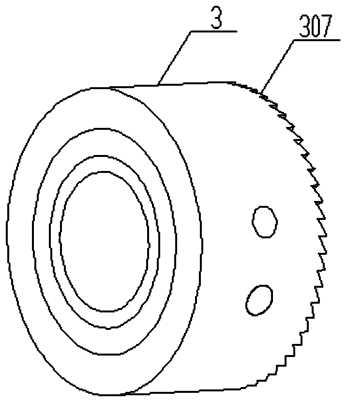
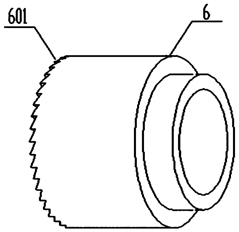
[0034] Such as figure 1 As shown, the screw braking device for automatic doors of vehicles of the present invention includes a driving motor and a screw transmission mechanism. The driving motor and the screw transmission mechanism belong to the prior art and will not be described in detail. A brake box is arranged between the driving motor and the screw transmission mechanism. The brake box includes a brake box 1, a main brake 3, an auxiliary brake 6, an unlocking disc 303 and a transmission main shaft 301, the drive motor, the screw transmission mechanism, The brake boxes are all installed on the fixed frame of the automatic door of the vehicle, and the fixed frame belongs to the prior art, and will not be described in detail.

[0035] Wherein the main brake 3 is installed with the transmission main shaft 301 through the first bearing 312, the auxiliary brake 6 is installed with the brake box 1 through the second bearing 7, and a driving disc 302 is arranged on the transmiss...

Embodiment 2

[0052] This embodiment is an improvement made on the basis of Embodiment 1. For the same content in this embodiment as Embodiment 1, please refer to the content disclosed in Embodiment 1 for understanding, and no repeated description is made here; the disclosure in Embodiment 1 The content should also be taken as the content disclosed in this embodiment.

[0053] Such as figure 1 , in this embodiment, the axial guide mechanism includes two guide rails and sliders installed in the guide rails, the two guide rails are respectively arranged on the inner wall surfaces corresponding to both sides of the brake box body 1, and the shaft of the guide rails and the transmission main shaft 301 The center lines are parallel; the slider is set on the main brake 3, and the two sliders are arranged in axisymmetric manner, and the two sliders are matched with the two guide rails; the spring return mechanism is a compression spring, and the compression spring is set on the transmission spindl...

Embodiment 3

[0055] This embodiment is an improvement made on the basis of Embodiment 1. For the same content in this embodiment as Embodiment 1, please refer to the content disclosed in Embodiment 1 for understanding, and no repeated description is made here; the disclosure in Embodiment 1 The content should also be taken as the content disclosed in this embodiment.

[0056] In this embodiment, the axial guide mechanism includes a long guide hole and a guide pin installed in the long hole. The long guide hole is arranged on the corresponding wall surfaces on both sides of the brake box 1. The long guide hole and the transmission spindle The axis lines of 301 are parallel; the guide pins are arranged on the main brake 3, and the two guide pins are arranged axisymmetrically, and the two guide pins are matched and installed with the two guide slots; one end of the guide pins passes through The thread is installed on the main brake, and the other end extends out of the brake box through the g...


PUM


Abstract

The invention discloses a lead screw braking device for vehicle automatic doors. The device comprises a driving motor, and a lead screw transmission mechanism, wherein a braking box is arranged between the driving motor and the lead screw transmission mechanism, and the braking box comprises a braking box body, a main brake, an auxiliary brake, an unlocking disc and a transmission main shaft. Thevehicle automatic doors realize opening and locking through the lead screw transmission mechanism, and a rotary damper between the main brake and the unlocking disc in the braking box randomly controls separation and engagement between the main brake and the auxiliary brake, so that opening and locking of the vehicle automatic doors are controlled, and the damping performance is kept stable and unchanged in the long-time operation process; and the lead screw braking device for the vehicle automatic doors realizes braking of the lead screw transmission mechanism with high reliability in a limited space, and is suitable for passenger car automatic doors, rail transit vehicle automatic doors and platform automatic doors, and has a good application prospect.

Description

Technical field: [0001] The invention relates to a lead screw braking device for an automatic door of a vehicle, which belongs to the technical field of rail transit. Background technique: [0002] With the vigorous development of rail transit, automatic doors such as sliding doors, external doors, and hidden doors are widely used in rail transit vehicle doors and platform screen doors. The unlocking device has become the key technology of automatic doors. At present, the domestic automatic door screw brake device has reliability problems due to design and manufacturing reasons after many years of use. Chinese patent 201810359047.5 discloses a plug-in door drive mechanism, including a drive motor installed at the end of the fixed frame, a lead screw connected to the output end of the drive motor, and a nut sub-assembly for driving the door body on the lead screw; The driving mechanism also includes a positioning device that cooperates with the nut sub-assembly to realize t...

Claims


Application Information

Patent Timeline
Patent Type & Authority Applications(China)
IPC IPC(8): E05F15/652
CPCE05F15/652E05Y2900/518E05Y2900/531
Inventor 童海波田兴华
Owner IVY MACHINERY NANJING
Why Eureka
Try Eureka