Top-down slippage preventing fixing and limiting device

A top-down, limit device technology, applied in the direction of output power conversion device, support structure installation, connecting components, etc., can solve the problems of easy falling off of fasteners, low installation accuracy, poor control, etc., to achieve It is convenient for installation and later maintenance, avoids potential safety hazards, and is convenient for packaging and handling

Active Publication Date: 2020-06-09
XIAN YONGDIAN ELECTRIC
View PDF5 Cites 2 Cited by
  • Summary
  • Abstract
  • Description
  • Claims
  • Application Information

AI Technical Summary

Problems solved by technology

Because it has no self-locking and anti-off functions, the bolts are easy to loosen during operation, and the fasteners are easy to fall off, posing safety hazards; and the infinite position design, the installation accuracy is not high
The existing vertical and longitudinal installation methods include two types: the first method installs L-shaped lead-out ends at the four corners of the bottom side of the power electronic device, fixes it to the bottom plate of the converter device through bolts, and installs an inverted terminal on the bottom side of the power electronic device. The L-shaped lead-out end is fixed to the fixed beam of the converter device next to it by bolts; in this installation method, the extended L-shaped fixed lead-out end increases the volume of the power electronic device, which is not conducive to the miniaturization and lightweight design of the power electronic device ; It is also necessary to reserve the operating space for the operator, which takes up a lot of space, which is not conducive to the miniaturization and lightweight design of the converter device; it is inconvenient to install and maintain, and it is necessary to disassemble the bolts of each fixed point one by one, and use each L-shaped fixed lead-out end At least 2 fixing bolts are required for calculation, and at least 8 bolts need to be disassembled and assembled for 4 L-shaped fixed outlets, which is time-consuming and laborious; during later maintenance, there is a danger of falling bolts and spring washers during disassembly and assembly
The second installation method realizes mechanical fixation through the long longitudinal screw. The nut used when the long longitudinal screw is fixed to the bottom plate of the device is easy to loosen during the vibration of the vehicle running. By adding spring washers to the nut fixed to the bottom plate of the device, the long screw can prevent loosening. , but when the device is detached from the converter device, the spring washer is easy to fall from the bottom of the screw into the converter device, posing a safety hazard; in order to prevent the spring washer from falling out, the processing length of the mounting thread at the bottom of the long screw can be limited. In the application, there are processing errors, processing errors of the power electronic device frame, and installation errors. The superposition of the three errors, the precision of the thread length limit of the long screw is high, and it is difficult to control in practical applications; The depth is limited, and the installation accuracy is not high

Method used


Image

  • Top-down slippage preventing fixing and limiting device
  • Top-down slippage preventing fixing and limiting device
  • Top-down slippage preventing fixing and limiting device

Examples


Embodiment

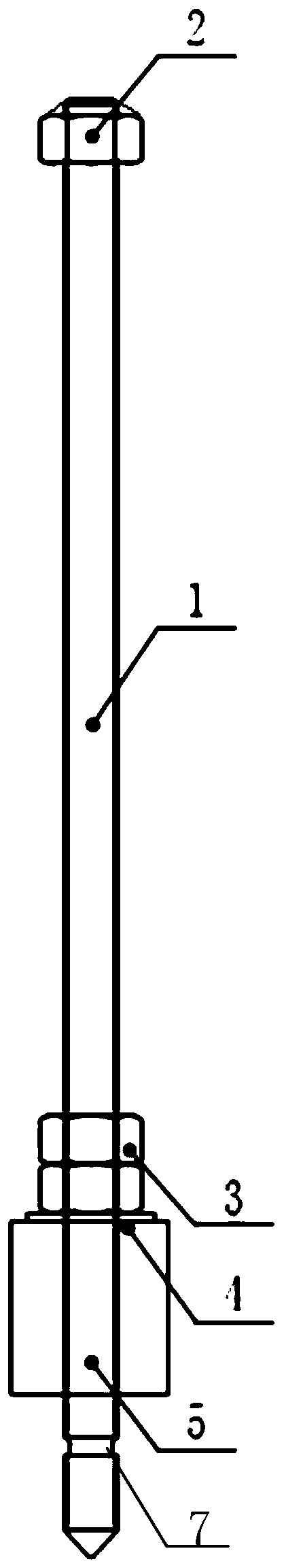
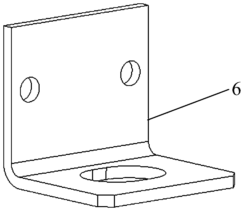
[0030] see Figure 1-3As shown, the present invention provides a top-down anti-slip fixing and limiting device, including a screw assembly installed in the power unit from top to bottom. assembly and disassembly; the screw assembly includes a long screw 1, and the top of the long screw 1 is welded with a nut 2. When the screw assembly is assembled in the power unit, the bottom of the vertical long screw 1 is a positioning piece 6, a self-locking The structure 3 , the spring pad 4 , the support column 5 , and the distance L1 between the top of the self-locking structure 3 and the positioning piece 6 is smaller than the height L2 of the support column 5 .

[0031] Preferably, the nut 2 is a hexagonal nut, and the hexagonal nut is welded to the top of the long screw 1. When installing the power unit to the inverter, the long screw 1 passes through the frame of the power unit from top to bottom and inserts it into the installation hole of the bottom plate of the inverter. Carry o...


PUM


Abstract

The invention belongs to the technical field of rail traffic power electronic equipment and relates to a top-down slippage preventing fixing and limiting device. The top-down slippage preventing fixing and limiting device comprises a screw assembly mounted in a power unit from top to bottom, the screw assembly moves up and down to assemble and detach the power unit and a bottom plate of a converter device, the screw assembly comprises a long screw, a nut is welded to the top of the long screw, a positioning sheet, a self-locking structure, an elastic pad and a supporting column are successively distributed from top to bottom at the bottom of the vertical long screw, and the distance L1 from the top of the self-locking structure to the positioning sheet is smaller than the height L2 of a supporting column. The top-down slippage preventing fixing and limiting device is convenient and rapid to operate, and is assembled without occupying a cabinet space, so that the space utilization ratiocan be improved, and it is favorable to miniaturize the power unit and the current converter device. The mounting reliability and availability of the device can be improved as a result of a self-locking slippage preventing design of the screw assembly.

Description

technical field [0001] The invention belongs to the technical field of rail transit power electronic devices, and relates to a top-down anti-slip fixing and limiting device. Background technique [0002] Rail transit electric locomotives, EMUs, and urban rail vehicle equipment involve a large number of mechanical fixation of power electronic devices. There are mainly two ways of equipment fixation: horizontal installation and vertical installation. Installation maintenance and reliable operation play an important role. At present, there are many horizontal installation applications of power electronic devices. In special fields such as urban rail transit vehicles, some devices are installed vertically. However, vertical installation is limited by space and personnel operating angles. higher requirements. [0003] In the existing horizontal and horizontal installation method, a fixed block is installed inside the power electronic device, and the mechanical fixation is reali...

Claims


Application Information

Patent Timeline
Patent Type & Authority Applications(China)
IPC IPC(8): F16B13/04H02M1/00H05K7/14
CPCF16B13/04H02M1/00H05K7/14
Inventor 马瑞曹琳王志强刘雄杜小渊廉琳逯玉成
Owner XIAN YONGDIAN ELECTRIC
Why Eureka
Try Eureka