
Waste oil collector

A waste oil collection and piston sleeve technology, applied in the lubrication of machines/engines, shafts, and engines, etc., can solve the problems of large stress on the bearing seal ring, affecting the working efficiency of the fan, and losing the lubrication effect, and achieves extended service life, The high frequency of action and the effect of avoiding the backflow of waste oil

Inactive Publication Date: 2020-06-09
ZHEJIANG WEIDUN MACHINERY TECH
View PDF8 Cites 1 Cited by
  • Summary
  • Abstract
  • Description
  • Claims
  • Application Information

AI Technical Summary

Problems solved by technology

However, as the fan bearings run for a long time to generate heat and continue to oxidize, the lubricating grease originally injected into the bearing will continue to harden and lose its lubricating effect; Grease and debris generated by the internal friction of the bearing will accelerate the wear of the bearing and affect the working efficiency of the fan

Method used


Image

  • Waste oil collector
  • Waste oil collector
  • Waste oil collector

Examples


Embodiment Construction

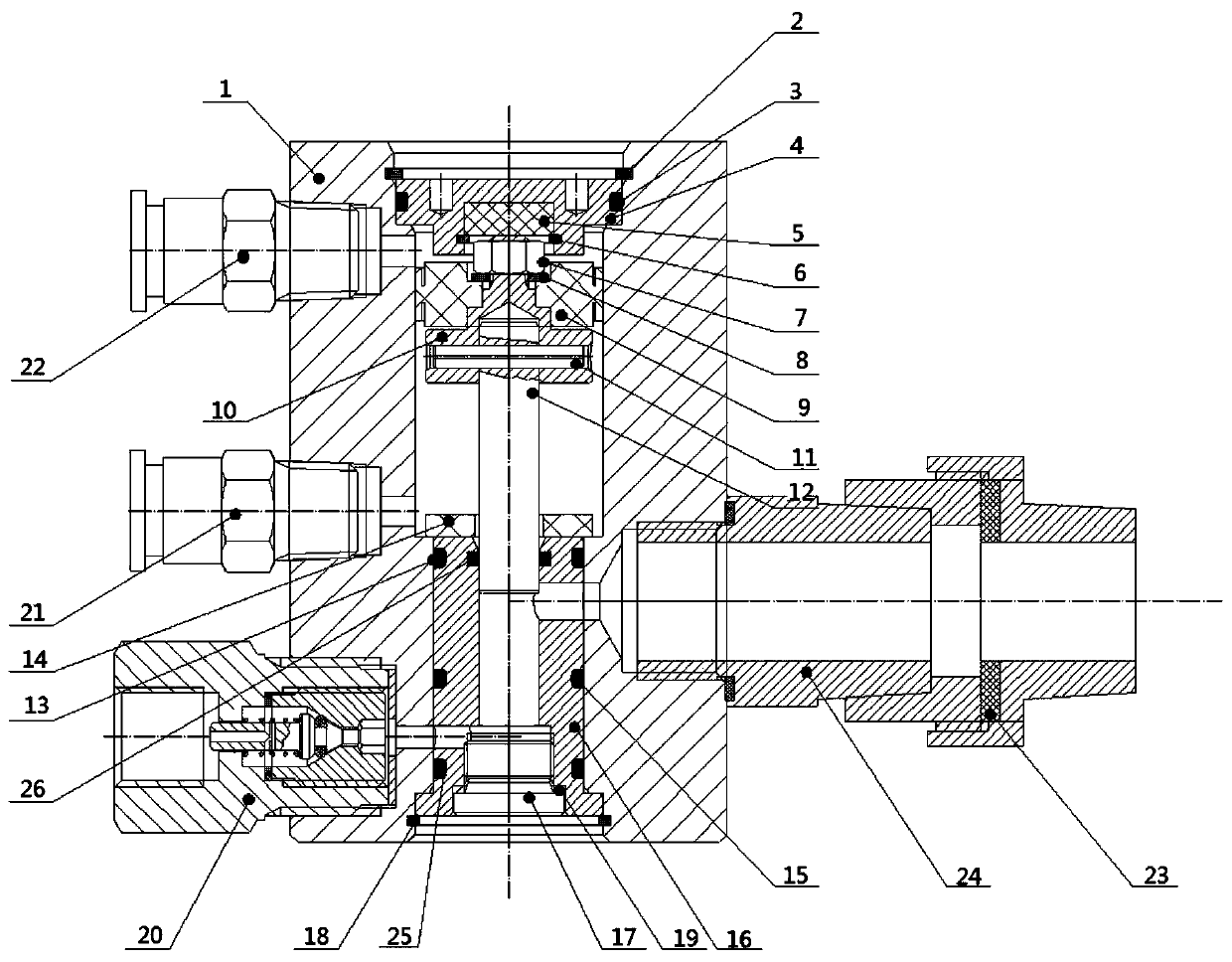
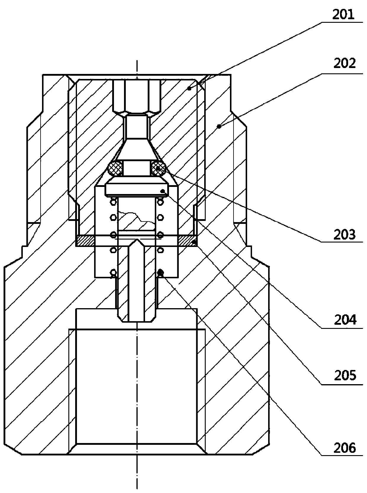
[0018] Such as figure 1 As shown, a waste oil collector includes a housing 1, a piston 12, a piston sleeve 16, a first air pipe joint 21, a second air pipe joint 22 and a one-way valve assembly 20; the piston 12 is arranged on the housing 1, the piston sleeve 16 is arranged on the lower end of the piston 12 and cooperates with it, and the top end of the piston 12 is provided with a cylinder plunger seal 9, so that the cylinder plunger seal 9 moves up and down to form two isolated air Cavity; the left side of the housing 1 is provided with the first air pipe joint 21 and the second air pipe joint 22, the first air pipe joint 21 communicates with the air chamber at the lower end of the cylinder plunger sealing ring 9, The second air pipe joint 22 communicates with the air cavity at the upper end of the cylinder plunger sealing ring 9; The bottom of the casing 1 is connected to the bottom; the right side of the housing 1 is threaded with an adapter assembly 24 , and the adapter ...


PUM


Abstract

The invention discloses a waste oil collector. The waste oil collector comprises a shell, a piston, a piston sleeve, a first air pipe connector, a second air pipe connector and a one-way valve assembly, the piston is arranged in the shell, the piston sleeve is arranged at the lower end of the piston and matched with the piston, an air cylinder plunger sealing ring is arranged at the top end of thepiston, the first air pipe connector and the second air pipe connector are arranged on the left side of the shell, the first air pipe connector communicates with an air cavity in the lower end of theair cylinder plunger sealing ring, the second air pipe connector communicates with an air cavity in the upper end of the air cylinder plunger sealing ring, the one-way valve assembly is fixedly installed at the lower end of the left side of the shell and communicates with the bottom of the piston sleeve, and an adapter assembly is arranged on the right side of the shell and communicates with thetop of the piston sleeve. According to the waste oil collector, compressed gas is adopted as a power source, the piston action frequency is high, the vacuum degree is high, and the working efficiencyis greatly improved.

Description

technical field [0001] The invention relates to the technical field of mechanical lubrication, in particular to a waste oil collector. Background technique [0002] During the operation of large-scale equipment such as fans, it is necessary to continuously inject grease into the bearing to achieve the lubrication effect, reduce equipment wear, and maintain the normal operation of the equipment. However, as the fan bearings run for a long time to generate heat and continue to oxidize, the lubricating grease originally injected into the bearing will continue to harden and lose its lubricating effect; the waste lubricating grease will continue to accumulate, causing the bearing seal ring to be broken due to excessive force; long-term waste lubrication Grease and debris generated by the internal friction of the bearing will accelerate the wear of the bearing and affect the working efficiency of the fan. Therefore how to develop a kind of waste oil collector that can clean up th...

Claims


Application Information

Patent Timeline
Patent Type & Authority Applications(China)
IPC IPC(8): F16N31/02F16C33/66F04D29/06
CPCF04D29/063F16C33/6622F16C2360/46F16N31/02F16N2210/14F16N2210/16
Inventor 罗园梁
Owner ZHEJIANG WEIDUN MACHINERY TECH
Learn More