Portable baton

A portable, baton technology, applied in batons, weapon types, weapons without explosives, etc., can solve the problems of large space occupation, long baton length, inconvenient carrying, etc., and achieve the effects of convenient operation, enhanced connection, and simple structure.

Inactive Publication Date: 2020-06-09
安徽蓝剑警用装备制造有限公司
View PDF7 Cites 1 Cited by
  • Summary
  • Abstract
  • Description
  • Claims
  • Application Information

AI Technical Summary

Problems solved by technology

But the length of the baton in this technical scheme is lo

Method used


Image

  • Portable baton
  • Portable baton
  • Portable baton

Examples


Embodiment 1

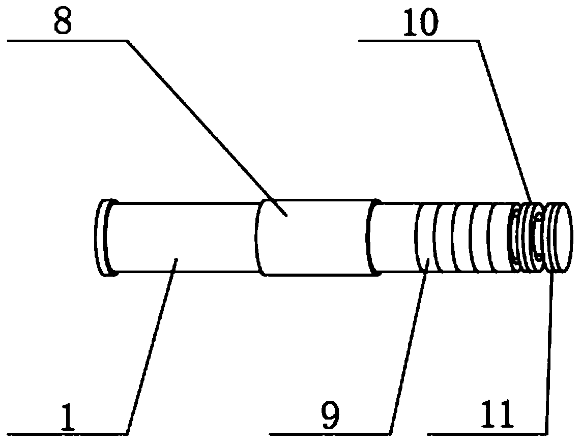
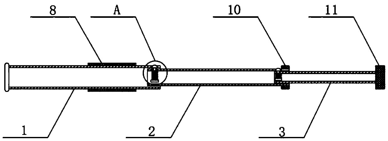
[0026] Such as Figure 1-3 As shown, a portable baton includes an outer tube 1, a middle tube 2 and an inner tube 3,

[0027] The outer tube 1 is movably inserted into the middle tube 2, and the middle tube 2 is movably inserted into the inner tube 3. Both the middle tube 2 and the inner tube 3 are provided with clamping devices, and the threaded section 9 provided on the side wall of the outer tube 1 is threaded. There is an internally threaded sleeve 8, the threaded section 9 is located at the right end of the outer tube 1, the length of the threaded section 9 is a quarter of the total length of the outer tube 1, and the end of the middle tube 2 away from the outer tube 1 is fixedly sleeved with a first screw rod 10. The end of the inner tube 3 away from the middle tube 2 is connected with a second screw 11, and the inner threaded sleeve 8 is matched with the first screw 10 and the second screw 11;

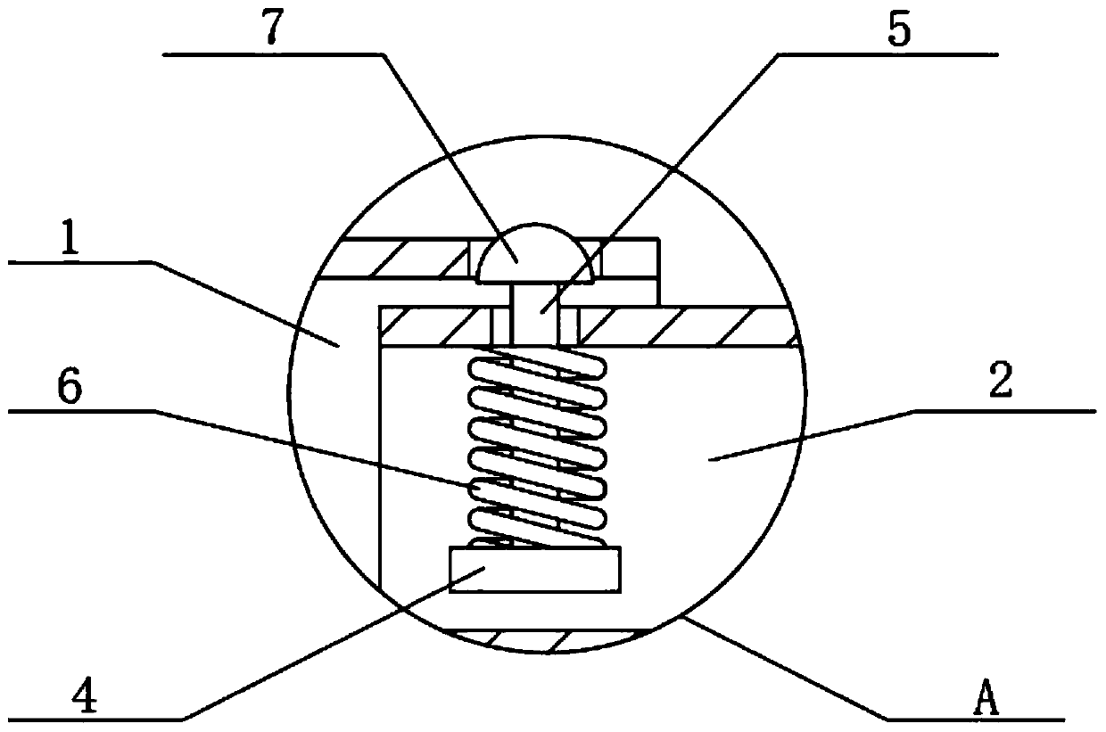
[0028] The clamping device includes a limiting plate 4, the upper end of t...

Embodiment 2

[0032] Such as Figure 1-3 As shown, a portable baton includes an outer tube 1, a middle tube 2 and an inner tube 3,

[0033] The outer tube 1 is movably inserted into the middle tube 2, and the middle tube 2 is movably inserted into the inner tube 3. Both the middle tube 2 and the inner tube 3 are provided with clamping devices, and the threaded section 9 provided on the side wall of the outer tube 1 is threaded. There is an internally threaded sleeve 8, the threaded section 9 is located at the right end of the outer tube 1, the length of the threaded section 9 is a quarter of the total length of the outer tube 1, and the end of the middle tube 2 away from the outer tube 1 is fixedly sleeved with a first screw rod 10. The end of the inner tube 3 away from the middle tube 2 is connected with a second screw 11, and the inner threaded sleeve 8 is matched with the first screw 10 and the second screw 11;

[0034] The clamping device includes a limiting plate 4, the upper end of t...


PUM


Abstract

The invention relates to the technical field of batons, in particular to a portable baton. The portable baton comprises an outer pipe, a middle pipe and an inner pipe, wherein the middle pipe is movably connected into the outer pipe in an inserting mode, the inner pipe is movably connected into the middle pipe in an inserting mode, clamping devices are arranged in the middle pipe and the inner pipe, and a threaded section formed in the side wall of the outer pipe is in threaded connection with an inner threaded sleeve; and through the clamping devices, the relative positions of the outer pipe,the middle pipe and the inner pipe are fixed, external force is applied to the middle pipe and the inner pipe, then the middle pipe and the inner pipe are pushed into the outer pipe, the outer pipe,a first screw rod and a second screw rod abut against one another, and the inner threaded sleeve is connected with the threaded section, the first screw rod and the second screw rod at the same time,so that the relative positions of the outer pipe, the middle pipe and the inner pipe are fixed. According to the baton designed by the technical scheme, the length can be flexibly changed, the baton is convenient to carry, the relative positions of the outer pipe, the middle pipe and the inner pipe are fixed through the inner threaded sleeve, the threaded section, the first screw rod and the second screw rod, the structure is simple, operation is convenient, and the fixing effect is good.

Description

technical field [0001] The invention relates to the technical field of batons, in particular to a portable baton. Background technique [0002] Baton is a must-have police weapon for front-line public security officers in China. It has a wide range of functions, strong aggressiveness, easy to carry, and tight defense. Various baton defense techniques were practiced. [0003] The application number is 201821135965.1, and the patent name is a security baton technical scheme. By setting a sliding sealing plate on the surface of the hand-held handle and setting the electric shock button inside the electric shock button groove, the user is prevented from accidentally touching and pressing the baton when holding the baton. The electric shock button will cause harm to oneself or the surrounding people, and reduce the safety hazard of the baton. By setting the rubber ring on the surface of the handle, the friction between the user's hand and the electric baton is effectively increa...

Claims


Application Information

Patent Timeline
IPC IPC(8): F41B15/02
CPCF41B15/027
Inventor 刘彬
Owner 安徽蓝剑警用装备制造有限公司
Why Eureka
Try Eureka