A drop test equipment for electronic products

A technology for testing equipment and electronic products, which is used in impact testing, testing of machine/structural components, measuring devices, etc., and can solve problems such as affecting the effect and accuracy of drop testing of electronic products, inconvenient operation, and inability to test height stability adjustment. , to achieve the effect of improving the effect and accuracy of the drop test, improving the convenience, and facilitating the drop test.

Active Publication Date: 2020-09-22
陈锋武
View PDF11 Cites 0 Cited by
  • Summary
  • Abstract
  • Description
  • Claims
  • Application Information

AI Technical Summary

Problems solved by technology

[0003] The existing electronic product drop test equipment is inconvenient to operate, unable to stably adjust the test height, and to flexibly select the test environment, which affects the effect and accuracy of the drop test of electronic products

Method used


Image

  • A drop test equipment for electronic products
  • A drop test equipment for electronic products
  • A drop test equipment for electronic products

Examples


Embodiment 1

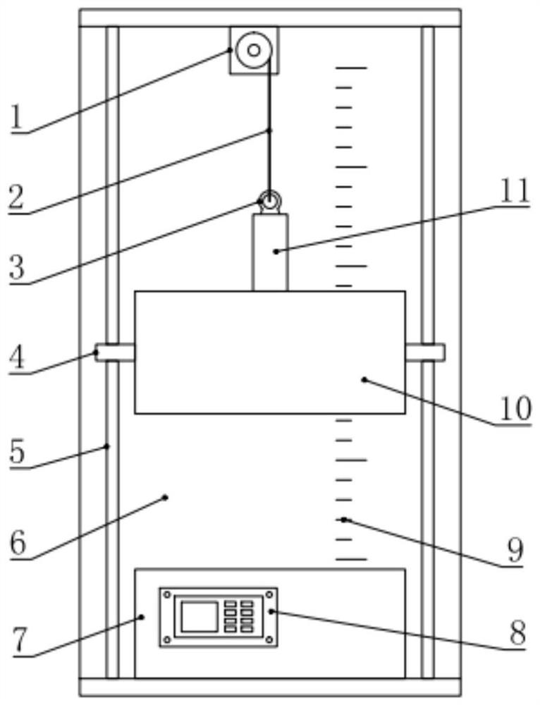
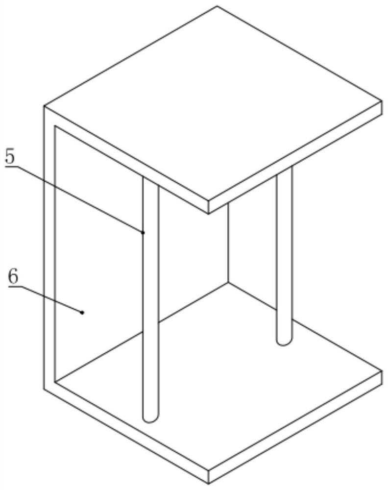
[0020] see Figure 1-2 , in an embodiment of the present invention, a drop test device for electronic products includes a U-shaped frame 6, a drop mounting seat 10 is provided on the inner side of the U-shaped frame 6, and a guide is respectively installed and fixed on the left and right sides of the drop mounting seat 10. Ring 4, the guide ring 4 is cooperating and slidingly provided with a guide rod 5, the upper and lower ends of the guide rod 5 are respectively connected and fixed with the inner top and inner bottom of the U-shaped frame 6, and the drop control assembly is installed in the drop mounting seat 10, The inner top of the U-shaped frame 6 is installed and fixed with a winding device 1, the winding device 1 is connected with the drop control assembly through the first rope 2, and the inner bottom of the U-shaped frame 6 is installed and fixed with a drop base 7. A drop bearing assembly is installed in the drop base 7 .

[0021] In the embodiment of the present in...

Embodiment 2

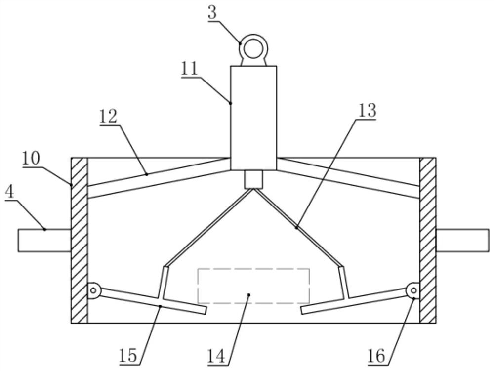
[0023] see Figure 1-7 , the difference between this embodiment and embodiment 1 is:

[0024] In this example, if image 3 with 4 As shown, the drop mount 10 is a cylindrical barrel structure with both ends open, and the drop control assembly includes a first telescopic cylinder 11, a diagonal strut 12, a second rope 13, a support rod 15 and a hinge support 16. The first telescopic cylinder 11 is arranged on the upper side of the middle part of the drop mounting base 10, and the first telescopic cylinder 11 is connected and fixed to the inner wall of the drop mounting base 10 through a plurality of diagonal struts 12 distributed in the circumferential direction. The oblique strut 12 can stably support the first telescopic cylinder 11; the inner lower part of the drop mount 10 is circumferentially distributed with a plurality of hinge supports 16, and the hinge supports 16 are hingedly provided with a support rod 15, and the The number of the support rods 15 and the diagonal...


PUM


Abstract

The invention relates to the field of electronic product testing, especially to electronic product drop test equipment. The electronic product drop test equipment comprises a U-shaped frame, and a falling mounting base is arranged on the inner side of the U-shaped frame; the left side and the right side of the falling mounting base are each fixedly provided with a guide ring; a guide rod is slidably arranged in the guide ring in a matched manner; the upper and lower ends of the guide rod are fixedly connected with the inner top and the inner bottom of the U-shaped frame respectively; a fallingcontrol assembly is mounted in the falling mounting base, a winding device is fixedly mounted at the inner top of the U-shaped frame and connected with the falling control assembly through a first rope, a falling base is fixedly mounted at the inner bottom of the U-shaped frame, and a falling bearing assembly is mounted in the falling base. According to the invention, the operation is convenient,the test height can be stably adjusted, the test environment can be flexibly selected, and the drop test effect and accuracy of the electronic product are improved.

Description

technical field [0001] The invention relates to the field of electronic product testing, in particular to an electronic product drop testing device. Background technique [0002] The drop test is a common test in safety testing, which simulates the situation where the product falls during carrying or use, and is used to test whether the product will cause danger when it falls. Smart electronic products, such as mobile phones and tablet computers, are consumer electronic products. In order to ensure their performance, smart electronic products need to be dropped tested during production. [0003] The existing electronic product drop test equipment is inconvenient to operate, unable to stably adjust the test height, and to flexibly select the test environment, which affects the effect and accuracy of the drop test of electronic products. Therefore, in view of the above status quo, it is urgent to develop a drop test device for electronic products to overcome the shortcomings ...

Claims


Application Information

Patent Timeline
Patent Type & Authority Patents(China)
IPC IPC(8): G01M7/08
CPCG01M7/08
Inventor 陈锋武
Owner 陈锋武
Why Eureka
Try Eureka