Supercharge Your Innovation With Domain-Expert AI Agents!

Bridge internal crack nondestructive testing equipment

A non-destructive testing technology for internal cracks, applied in measuring devices, using sound waves/ultrasonic waves/infrasonic waves to analyze solids, using sound waves/ultrasonic waves/infrasonic waves for material analysis, etc., can solve problems such as bridge cracks and defects that cannot be detected, and avoid detection Dead angle, the effect of improving detection efficiency

Pending Publication Date: 2020-06-09
广西壮族自治区特种设备检验研究院
View PDF0 Cites 4 Cited by
  • Summary
  • Abstract
  • Description
  • Claims
  • Application Information

AI Technical Summary

Problems solved by technology

[0005] The purpose of the present invention is to provide a non-destructive detection equipment for bridge internal cracks to solve the problem in the prior art that only cracks on the bridge surface can be detected, and cracks and defects inside the bridge cannot be detected

Method used


Image

  • Bridge internal crack nondestructive testing equipment
  • Bridge internal crack nondestructive testing equipment
  • Bridge internal crack nondestructive testing equipment

Examples


Embodiment 1

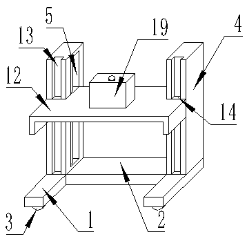
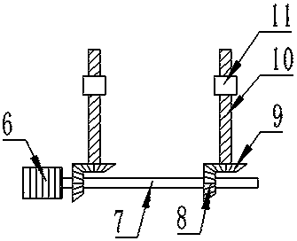
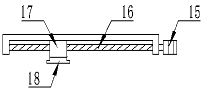
[0021] Such as figure 1 As shown, the embodiment of the present invention provides a non-destructive testing device for internal cracks in bridges. The non-destructive testing device includes two symmetrically arranged support plates 1, and the two support plates 1 are connected by a connecting plate 2. The support plates 1 The bottom of the plate 1 is equipped with a pulley 3; the upper surfaces of the two support plates 1 are fixed with a support column 4, and a height adjustment mechanism is installed between the two support columns 4; the height adjustment mechanism includes a lifting plate 12, and the lifting The bottom of the plate 12 is provided with a translation detection mechanism, and the translation detection mechanism includes an ultrasonic transmitting end 18 .

[0022] The non-destructive testing equipment for cracks inside the bridge uses the ultrasonic transmitter 18 to achieve the purpose of non-destructive testing. It can detect cracks and defects inside the...

Embodiment 2

[0031] Such as figure 1 As shown, in yet another embodiment provided by the present invention, a remote communication module 19 is installed on the upper surface of the lifting plate 12 , and the remote communication module 19 is connected to the ultrasonic transmitting end 18 .

[0032] Ultrasonic waves are transmitted to the bridge through the ultrasonic transmitting end 18, and transmitted to the central processing unit by the remote communication module 19, and the height and position of the transmitted signal are displayed on the display component by the central processing unit, so that the size of the defect can be judged, which is convenient for inspection personnel Intuitively check the defects inside the bridge.


PUM


Abstract

The invention is applicable to the technical field of nondestructive testing, and provides bridge internal crack nondestructive testing equipment which comprises two symmetrically arranged supportingplates, the two supporting plates are connected through a connecting plate, and pulleys are mounted at the bottoms of the supporting plates; supporting stand columns are fixed to the upper surfaces ofthe two supporting plates, and a height adjusting mechanism is installed between the two supporting stand columns. The height adjusting mechanism comprises a lifting plate, and a translation detection mechanism is arranged at the bottom of the lifting plate and comprises an ultrasonic transmitting end. According to the invention, cracks and defects in a bridge can be detected; the ridge internalcrack nondestructive testing equipment can detect the condition of the bridge in real time, does not affect normal use of the bridge, can adjust the height of the ultrasonic transmitting end and the height of the bridge body in cooperation with the height adjusting mechanism and the translation detection mechanism, achieves the optimal detection effect, and can detect the whole bridge body throughthe pulleys at the bottom.

Description

technical field [0001] The invention belongs to the technical field of non-destructive testing, in particular to a non-destructive testing device for internal cracks in bridges. Background technique [0002] A bridge refers to a structure erected on rivers, lakes and seas to allow vehicles and pedestrians to pass smoothly. A bridge generally consists of a superstructure, a substructure, a support and ancillary structures. In order to ensure the smooth passage of the bridge and avoid accidents such as collapse, To ensure the personal safety of passers-by, bridges need to be inspected regularly. [0003] When inspecting bridges, ordinary inspection tools can only detect cracks and defects on the bridge surface, but cannot detect abnormalities and defects in the internal structure of the bridge. If there are defects in the internal structure of the bridge, there will be huge safety hazards. endanger personal safety. [0004] Based on the above technical problems, there is an ...

Claims


Application Information

Patent Timeline
IPC IPC(8): G01N29/04G01N29/22G01N29/265
CPCG01N29/04G01N29/225G01N29/265G01N2291/0289
Inventor 魏玉伟罗立霄朱政果韦云部江村
Owner 广西壮族自治区特种设备检验研究院
Features
  • R&D
  • Intellectual Property
  • Life Sciences
  • Materials
  • Tech Scout
  • Unparalleled Data Quality
  • Higher Quality Content
  • 60% Fewer Hallucinations
Learn More