Eureka AIR delivers breakthrough ideas for toughest innovation challenges, trusted by R&D personnel around the world.

A method for determining the effective monitoring distance of hydraulic fracturing microseismic in coal mines

A technology of hydraulic fracturing and method determination, which is applied in seismology, seismic signal processing, geophysical measurement, etc. It can solve the problems of small seismic energy, limited propagation distance, and unrecoverable geophones, etc., and achieves easy implementation and simple operation Effect

Active Publication Date: 2022-07-01
CHONGQING UNIV
View PDF0 Cites 0 Cited by
  • Summary
  • Abstract
  • Description
  • Claims
  • Application Information

AI Technical Summary

Problems solved by technology

The disadvantage of installing the geophone in the borehole is that additional drilling needs to be drilled under the mine, and the geophone cannot be recovered
However, due to the excessive pursuit of grid format, the geophone is far away from the source point, and the microseismic energy generated by hydraulic fracturing in coal mines is small, and the propagation distance is limited. This method is not suitable for underground hydraulic fracturing microseismic monitoring.
[0004] Before the implementation of microseismic monitoring in coal mines, a calibration shot is usually placed. The calibration shot is only used to measure the wave velocity, and the amplitude and frequency attenuation characteristics of the microseismic waves generated by blasting are not fully utilized. As a result, many geophones placed in the actual monitoring process cannot detect microseismic waves. signal, wasted detector
In the microseismic monitoring of hydraulic fracturing in coal mines, there is no practical technical means to determine the geophone layout distance, which has caused difficulties and waste to the construction of microseismic monitoring

Method used


Image

  • A method for determining the effective monitoring distance of hydraulic fracturing microseismic in coal mines
  • A method for determining the effective monitoring distance of hydraulic fracturing microseismic in coal mines
  • A method for determining the effective monitoring distance of hydraulic fracturing microseismic in coal mines

Examples


Embodiment Construction

[0022] Below in conjunction with accompanying drawing and embodiment, the present invention will be further described:

[0023] The present invention includes the following steps:

[0024] Step 1. Set the calibration gun and arrange the detector to record the signal. Follow the steps below:

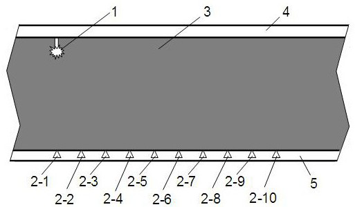
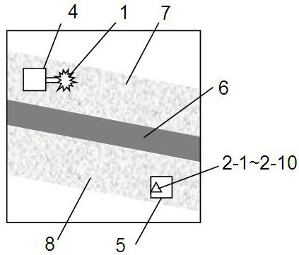
[0025] 11) As figure 1 and figure 2 As shown in the figure, the calibration shot blasting point 1 is selected in the roof rock tunnel 4 near the pre-fracturing reservoir 3; the geophones 2-1 to 2-10 are arranged at equal intervals in the bottom rock tunnel 5. increase sequentially.

[0026] The pre-fracturing reservoir 3 has a coal seam 6, a top plate 7 and a bottom plate 8; the roadway is arranged in the rock layer: the top plate 7 and the bottom plate 8, and the coal seam roadway is not excavated before the drainage reaches the standard and the gas danger is eliminated.

[0027] 12) Connect the geophone and the microseismic signal acquisition instrument, connect the microseismic ac...


PUM


Abstract

The invention discloses a method for determining the effective monitoring distance of hydraulic fracturing micro-seismic in a coal mine, which fully utilizes the amplitude and frequency attenuation characteristics of micro-seismic waves. 2. Extract the signal amplitude and centroid frequency; step 3, draw the amplitude attenuation curve; step 4, draw the frequency contour; step 5, determine the effective monitoring distance of microseismic. The technical effect of the invention is that reliable data is provided for the effective monitoring distance of micro-seismic in the hydraulic fracturing in the coal mine, and a technical scheme is provided for arranging the geophone and the mobile geophone in the construction process. The invention is suitable for microseismic monitoring of hydraulic fracturing in coal mines.

Description

technical field [0001] The invention belongs to the technical field of applied geophysics, and in particular relates to a method for determining the effective monitoring distance of a hydraulic fracturing micro-seismic in a coal mine. Background technique [0002] Microseismic monitoring technology is widely used in oil, natural gas, shale gas, coalbed methane, carbon dioxide storage, mining and other underground projects, and its main purpose is to monitor the fracture and fracture propagation behavior of reservoir stimulation. Gas underground in coal mines has undoubtedly become an energy source and is an important part of natural gas. Hydraulic fracturing technology can effectively increase the permeability of coal seams and promote efficient gas drainage. The promotion of hydraulic fracturing technology in coal mines requires the implementation of microseismic monitoring in coal mines. [0003] At present, the micro-seismic monitoring of hydraulic fracturing in coal mi...

Claims


Application Information

Patent Timeline
Patent Type & Authority Patents(China)
IPC IPC(8): G01V1/28G01V1/20G01V1/16G01V1/30
CPCG01V1/288G01V1/20G01V1/168G01V1/307G01V1/306G01V2210/144G01V2210/1429G01V2210/63G01V2210/62
Inventor 李全贵姜志忠胡千庭凌发平吴燕清许洋铖宋明洋胡良平张跃兵刘乐
Owner CHONGQING UNIV
Why Eureka
Eureka Blog
Learn More