Electrical connector and method for manufacturing the same

A technology for electrical connectors and manufacturing methods, which is applied to the components, connections, and assembly/disassembly of contact pieces of connecting devices, and can solve the problems of reducing manufacturing efficiency, reducing signal terminal transmission efficiency, and reducing the shielding performance of electrical connectors, etc. , to achieve the effect of simplifying the forming and cutting steps

Active Publication Date: 2021-06-18
DEYI PRECISION ELECTRONIC IND CO LTD PANYU
View PDF0 Cites 0 Cited by
  • Summary
  • Abstract
  • Description
  • Claims
  • Application Information

AI Technical Summary

Problems solved by technology

[0002] An existing commonly used electrical connector structure includes an insulating block and an upper row of terminal groups injection-molded with the insulating block, an intermediate shielding sheet and a lower row of terminal groups, wherein the upper and lower row of terminal groups include grounding terminals and signal terminals , the length of the front end of the grounding terminal is greater than that of the signal terminal. In order to ensure the shielding effect, the front end of the middle shielding sheet is located in front of the front end of the signal terminal. In the injection molding process, in order to facilitate the positioning of the terminal, the upper and lower row Two adjacent terminals in the terminal group are connected by a material bridge, and the side edges of the two outermost terminals have extensions to connect with the strip. After the injection molding is completed, not only the strip needs to be cut, but also the connection needs to be removed. The material bridge between adjacent terminals has a complicated process and reduces manufacturing efficiency. In addition, because the two outermost terminals and part of the extension are embedded in the insulating block together, it is equivalent to an increase in the width of the outermost terminal. In actual use Reduce the transmission efficiency of signal terminals and reduce the shielding performance of electrical connectors

Method used


Image

  • Electrical connector and method for manufacturing the same
  • Electrical connector and method for manufacturing the same
  • Electrical connector and method for manufacturing the same

Examples


Embodiment Construction

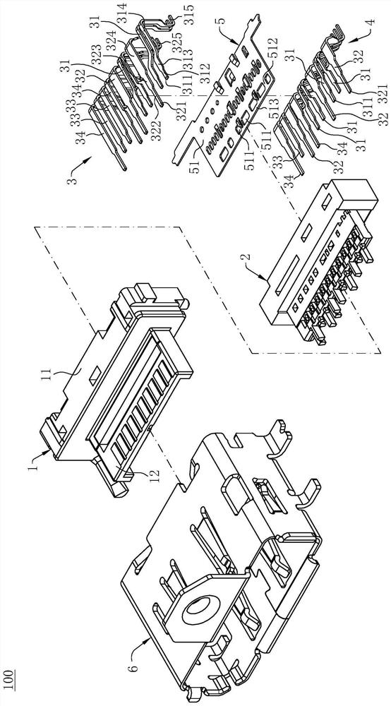
[0032] Such as figure 1 , Figure 4 and Figure 5As shown, this is the electrical connector 100 of the present invention, the electrical connector 100 is a Display Port receptacle for connecting with a Display Port plug (not shown), and the electrical connector 100 is used for Welded to a circuit board (not shown), in other embodiments, the electrical connector 100 can be an HDMI socket or a socket of other interfaces, for docking with an HDMI plug or a plug of other interfaces, the electrical connection The device 100 includes an insulating body 1, an insulator 2 accommodated on the insulating body 1, a first terminal row 3, a second terminal row 4 and a shielding member 5, and a metal shell 6 covers the insulating body 1. The exterior of body 1. Injection molding the insulator 2 on the periphery of the first terminal row 3 , the second terminal row 4 and the shielding member 5 at one time, and then on the first terminal row 3 , the second terminal row 4 , The outer perip...


PUM


Abstract

The invention discloses an electrical connector and a manufacturing method of the electrical connector, comprising injection molding of an insulator, a first terminal row, a second terminal row and a shielding member at one time, and the first terminal row and the second terminal row both include signal terminals and For the ground terminal, the front free end of the signal terminal has a first cutout portion, the front free end of the ground terminal has a second cutout portion, the shield has a main body located between the first terminal row and the second terminal row, and the main body is along the There is a space for giving way in the up and down direction. Viewed along the up and down direction, the projection of the first cutting part is located in the giving way space, and the cutting tool enters the giving way space to form the first cutting surface for the cutting of the first cutting part. The cutting tool is located at the front end of the insulator and cuts off the second cutting part to form a second cutting surface. The second cutting surface is located in front of the first cutting surface, and the front end of the main body is located between the first cutting surface and the second cutting surface. Between the cutting surfaces, the invention can simplify the forming and cutting steps on the basis of satisfying the transmission of high-frequency signals.

Description

【Technical field】 [0001] The invention relates to an electrical connector and a manufacturing method of the electrical connector, in particular to an electrical connector with a shield and a manufacturing method of the electrical connector. 【Background technique】 [0002] An existing commonly used electrical connector structure includes an insulating block and an upper row of terminal groups injection-molded with the insulating block, an intermediate shielding sheet and a lower row of terminal groups, wherein the upper and lower row of terminal groups include grounding terminals and signal terminals , the length of the front end of the grounding terminal is greater than that of the signal terminal. In order to ensure the shielding effect, the front end of the middle shielding sheet is located in front of the front end of the signal terminal. In the injection molding process, in order to facilitate the positioning of the terminal, the upper and lower row Two adjacent terminal...

Claims


Application Information

Patent Timeline
Patent Type & Authority Patents(China)
IPC IPC(8): H01R13/24H01R13/405H01R13/6585H01R43/20
CPCH01R13/24H01R13/405H01R13/6585H01R43/20
Inventor 蔡伦
Owner DEYI PRECISION ELECTRONIC IND CO LTD PANYU
Why Eureka
Try Eureka