

Transformer, power distribution box and power distribution area
A technology for distribution station and transformer, which is applied in transformer/inductance parts, transformer/reactor installation/support/suspension, transformer/inductor coil/winding/connection, etc. The problems such as exposed terminals of the incoming wires of the electric box and messy wiring have achieved the effects of reducing false electric shocks, convenient material collection, and standardized wiring
- Summary
- Abstract
- Description
- Claims
- Application Information
AI Technical Summary
Problems solved by technology
Method used
Image

Examples
specific Embodiment 1
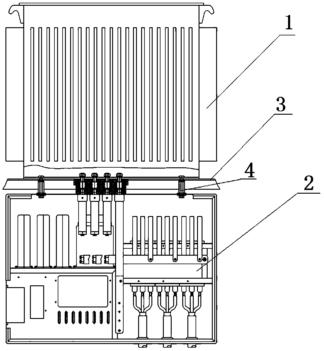
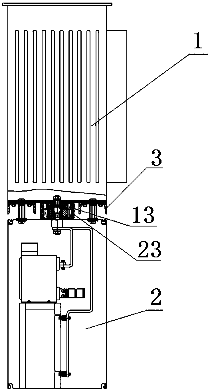
[0055] Such as figure 1 , figure 2 As shown, the distribution station area includes a transformer 1, a distribution box 2 and a beam structure 3. The improvement of the present invention is to improve the cable connection between the transformer 1 and the distribution box 2 to a plug connection. Specifically, this implementation In the example, the bottom wall of the transformer 1 shell is provided with a low-voltage outgoing line plug-in structure connected to the low-voltage side of the transformer inner core, and the top wall of the distribution box 2 is provided with a low-voltage incoming line plug-in structure connected with the electrical components in the box. The transformer 1 is located above the beam structure 3 , and the distribution box 2 is hoisted below the beam structure 3 through the bolt assembly 4 . The plug-in structure of the low-voltage outgoing line of the transformer 1 is connected with the plug-in structure of the low-voltage incoming line of the dis...
specific Embodiment 2
[0070] The difference from Embodiment 1 is that the side wall of the transformer housing is provided with a low-voltage outlet plug-in structure connected to the low-voltage side of the transformer, and the side wall of the distribution box is provided with a socket connected to the electrical components in the box. The low-voltage incoming line plug-in structure, the transformer and the distribution box are arranged horizontally on the beam structure. Since there is a certain height requirement between the distribution station area and the ground, the horizontal arrangement of the transformer distribution box can reduce the overall cost of the distribution station area. high. When the transformer and the distribution box are arranged horizontally, the low-voltage outgoing line plug-in structure and the low-voltage incoming line plug-in structure are respectively located in the front and rear directions of the transformer and the distribution box. In other embodiments, the low...
specific Embodiment 3
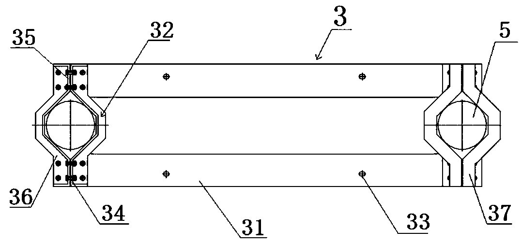
[0072]The difference from Example 1 is that the beam structure includes two pairs of beams, two pairs of hoops located at both ends of the beams, and a reinforcement plate is provided between the two pairs of beams, and the reinforcement plate is in the length direction of the two beams. They are arranged at intervals, and the reinforcement boards extend along the width direction of the two beams. The two pairs of beams and the reinforcement boards together form a frame structure to support the transformer and the distribution box. The beam structure has high strength. In other embodiments, the reinforcing plate may also be intersected between the two pairs of beams, and the two ends of the reinforcing plate are respectively located near the ends of the two pairs of beams, so that the strength of the beam structure is high. At this time, the low-voltage incoming line plug-in structure and the bared teeth outgoing line plug-in structure are located in the gap between the beam an...
PUM
 Abstract
Description
Claims
Application Information