
Oil groove iron scrap cleaning device for gear ring processing

A technology for cleaning devices and oil tanks, which is applied in the field of ring gear processing, and can solve problems such as collisions, falling into the oil tank, and falling off of the operator's suction pipe

Inactive Publication Date: 2020-06-12
怀化市恒裕实业有限公司
View PDF14 Cites 0 Cited by
  • Summary
  • Abstract
  • Description
  • Claims
  • Application Information

AI Technical Summary

Problems solved by technology

[0004] The object of the present invention is to provide a device for cleaning iron filings in an oil tank for gear ring processing, so as to solve the problem that when using the existing fully automatic liquid pool cleaning machine proposed in the above background technology, the operator needs to hold the liquid suction pipe to operate. Since the surface of the pumping tube has no fixing device and is relatively smooth, the operator may cause the problem that the pumping tube falls off from the hand during use and falls into the oil tank, which is inconvenient. At the same time, after the oil pumping is completed , the operator generally directly inserts the suction tube into the rectangular tube base, but because there is no good fixation between the suction tube and the rectangular tube base, when transferring to the washing machine, the suction tube will go back and forth inside the rectangular tube base Shakes and crashes

Method used


Image

  • Oil groove iron scrap cleaning device for gear ring processing
  • Oil groove iron scrap cleaning device for gear ring processing
  • Oil groove iron scrap cleaning device for gear ring processing

Examples


Embodiment 1

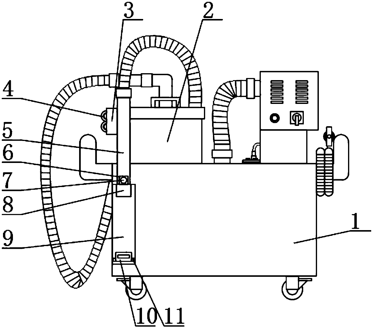
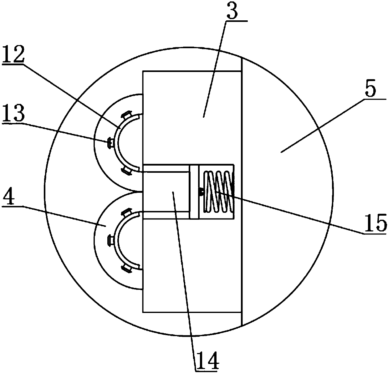
[0024] see Figure 1 to Figure 3 , the present invention provides a technical solution: a device for cleaning iron filings in an oil tank for gear ring processing, including a body 1, a rectangular tube seat 9 is provided on the front surface of the body 1, and a suction tube 5 is provided at the top of the rectangular tube seat 9 , the bottom end of the liquid suction tube 5 is in the inside of the rectangular tube seat 9, and one side surface of the liquid suction tube 5 is provided with an integrated rectangular block 3, and the inside of the rectangular block 3 is provided with a tension spring chamber 15, and the tension spring chamber 15 The top of the telescopic column 14 is connected with a telescopic column 14 by a tension spring, and the top of the telescopic column 14 is symmetrically provided with two integrated arc clamps 4, and the arc clamp 4 is on the outer surface of the rectangular block 3. By setting the arc clamp 4, the The operator can put his fingers insi...

Embodiment 2

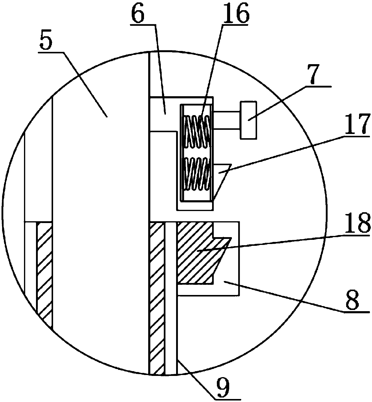
[0030] see Figure 1 to Figure 5 , the present invention provides a technical solution: a device for cleaning iron filings in an oil tank for gear ring processing, including a body 1, a rectangular tube seat 9 is provided on the front surface of the body 1, and a suction tube 5 is provided at the top of the rectangular tube seat 9 , the bottom end of the liquid suction tube 5 is in the inside of the rectangular tube seat 9, and one side surface of the liquid suction tube 5 is provided with an integrated rectangular block 3, and the inside of the rectangular block 3 is provided with a tension spring chamber 15, and the tension spring chamber 15 The top of the telescopic column 14 is connected with a telescopic column 14 by a tension spring, and the top of the telescopic column 14 is symmetrically provided with two integrated arc clamps 4, and the arc clamp 4 is on the outer surface of the rectangular block 3. By setting the arc clamp 4, the The operator can put his fingers insi...


PUM


Abstract

The invention discloses an oil groove iron scrap cleaning device for gear ring processing. The oil groove iron scrap cleaning device for gear ring processing comprises a machine body; a rectangular pipe seat is arranged on the front surface of the machine; a liquid pumping pipe is arranged at the top end of the rectangular pipe seat; the bottom end of the liquid pumping pipe is positioned in the rectangular pipe seat; an integrated rectangular block is arranged on side surface of the liquid pumping pipe; a tension spring chamber is formed in the rectangular block; the top end of the tension spring chamber is connected with a telescopic post; when an operator needs to hold the oil pumping pipe to perform an oil pumping operation, an arc-shaped clamp is dragged outwards vigorously first, andfingers of the operator can be clamped by the arc-shaped clamp, so that the oil pumping pipe can be fixed to a handle of the operator; the inconvenience that the oil pumping pipe falls off from the hand of the operator in a using process because the surface of the oil pumping pipe is too smooth can be avoided effectively; and an L-shaped connecting block and a fixed seat are arranged, so that theoil pumping pipe can be fixed to the interior of the rectangular pipe seat more stably.

Description

technical field [0001] The invention belongs to the technical field of ring gear processing, and in particular relates to a device for cleaning iron chips in an oil tank for ring gear processing. Background technique [0002] The ring gear is inlaid on the outer edge of the flywheel after being heated, and then fastened to the outer edge of the flywheel after cooling. It is used to mesh with the starter gear, drive the crankshaft to rotate, and start the engine. The ring gear is generally completed on the machine tool. However, when the machine tool is processing the ring gear, a large amount of iron filings will be generated inside the oil tank. If it is not cleaned in time, it will affect the normal operation of the machine tool. At present, most factories use a fully automatic liquid pool cleaning machine to clean the The iron filings inside the oil tank are cleaned, which greatly improves the efficiency of traditional manual cleaning, and at the same time prevents worker...

Claims


Application Information

Patent Timeline
IPC IPC(8): B23Q11/00
CPCB23Q11/0046
Inventor 廖庆云陈政南
Owner 怀化市恒裕实业有限公司
Features
  • Generate Ideas
  • Intellectual Property
  • Life Sciences
  • Materials
  • Tech Scout
  • Unparalleled Data Quality
  • Higher Quality Content
  • 60% Fewer Hallucinations
Learn More