
Height limiting device for roads and bridges

A technology for bridges and height limitation, applied in the municipal field, can solve the problems of inconvenience, pulling and deformation of the height limitation device, poor effect, etc., and achieve the effect of simple structure, impact resistance and ideal effect.

Inactive Publication Date: 2020-06-12
南京奥新可工程科技有限公司
View PDF7 Cites 1 Cited by
  • Summary
  • Abstract
  • Description
  • Claims
  • Application Information

AI Technical Summary

Problems solved by technology

Existing height-limiting devices such as "a height-limiting device" disclosed in Chinese patent No. 201721463147. In terms of mechanism, the height limiting device also includes at least two anti-falling wire ropes, one end of the anti-falling wire ropes is connected to the height limiting rod, and the connection points of each anti-falling steel wire rope and the height limiting rod are spaced along the extending direction of the height limiting rod. Arrangement, the other end of the anti-drop wire rope is connected to the device frame. For the height limit device of this structure, if the height limit vehicle passes, it needs to be rigidly collided. In severe cases, the entire height limit device may be destroyed. Pulling deformation will cause serious impact, and it is not portable and the effect is poor. At the same time, this kind of height limiting device is very inconvenient to set up and requires special equipment to realize. In addition, the existing height limiting device is generally lifted into the However, when it needs to be replaced, it needs to be removed with the help of an external crane or a jacking structure. Therefore, when the self-lifting mechanism is raised, it can only push the height-limiting pole into place and cannot be used in emergencies such as temporary maintenance or withdrawal from roadblocks. Removing the height limit rod

Method used


Image

  • Height limiting device for roads and bridges
  • Height limiting device for roads and bridges
  • Height limiting device for roads and bridges

Examples


Embodiment Construction

[0022] The following will clearly and completely describe the technical solutions in the embodiments of the present invention with reference to the accompanying drawings in the embodiments of the present invention. Obviously, the described embodiments are only some, not all, embodiments of the present invention. Based on the embodiments of the present invention, all other embodiments obtained by persons of ordinary skill in the art without making creative efforts belong to the protection scope of the present invention.

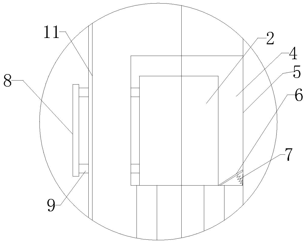
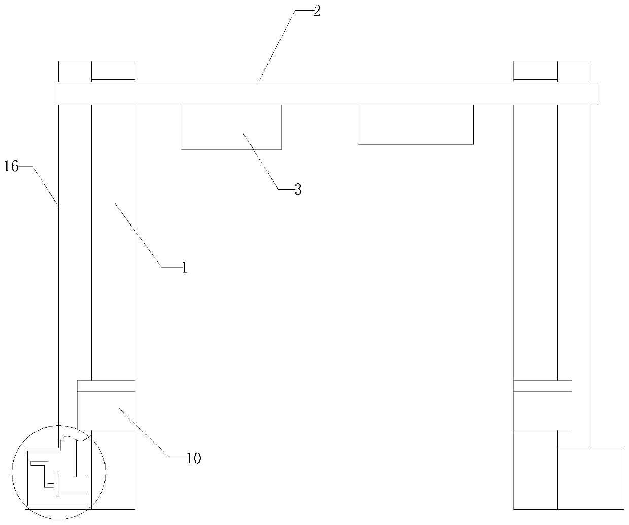
[0023] see Figure 1-4 , a height-limiting device for road bridges of the present invention includes a vertical frame 1 and a height-limiting frame 2, the vertical frame 1 is arranged on both sides of the height-limiting frame 2, and the top of the vertical frame 1 is provided with a placement cavity 4. The rear of the height limit frame 2 is provided with a buffer plate 8, the buffer plate 8 is provided with a connecting plate 9, one end of the connection pla...


PUM


Abstract

The invention discloses a height limiting device for roads and bridges. The device comprises a vertical frame and a height limiting frame, the vertical frames are arranged on the two sides of the height limiting frame. A containing cavity is formed in the top of the vertical frame. An opening is formed in the front of the top of the vertical frame in the traveling direction. The opening is connected with the placing cavity; the vertical frame is arranged in the placing cavity; a height limiting plate is arranged on the height limiting frame; an inclined plate is arranged at the position, in front of the height limiting frame, of the containing cavity; one end of the inclined plate is hinged with the vertical frame; a spring is also arranged in the placing cavity; one end of the spring is hinged to the other end of the inclined plate, and the other end of the spring is hinged in the placing cavity; the arranged height limiting frame achieves height limiting, and meanwhile, the situationthat the vertical frame is damaged and serious consequences are directly caused due to the fact that illegal vehicles collide with the height limiting device is avoided; impact of the illegal vehicles is effectively blocked through the arranged detachable structure, and the arranged lifting mechanism enables the height limiting frame to be simply installed on the vertical frame at the same time;and the structure is simple, and the effect is ideal.

Description

technical field [0001] The invention relates to the field of municipal technology, in particular to a height limiting device for roads and bridges. Background technique [0002] At present, in order to protect bridges, culverts, tunnels on the road, or some other reasons, it is necessary to set up height limiting devices at designated road positions. Existing height-limiting devices such as "a height-limiting device" disclosed in Chinese patent No. 201721463147. In terms of mechanism, the height limiting device also includes at least two anti-falling wire ropes, one end of the anti-falling wire ropes is connected to the height limiting rod, and the connection points of each anti-falling steel wire rope and the height limiting rod are spaced along the extending direction of the height limiting rod. Arrangement, the other end of the anti-drop wire rope is connected to the device frame. For the height limit device of this structure, if the height limit vehicle passes, it needs...

Claims


Application Information

Patent Timeline
Patent Type & Authority Applications(China)
IPC IPC(8): E01F13/00E01F13/04
CPCE01F13/00E01F13/048
Inventor 唐亚娟孟萍
Owner 南京奥新可工程科技有限公司
Learn More