Diesel engine with base provided with a shock absorber and installation method of diesel engine

An installation method and shock absorber technology, applied in the direction of spring/shock absorber, machine/engine, supporting machine, etc., can solve the problems of inflexible installation, large volume and heavy weight, etc., to reduce labor intensity and improve seismic performance , the effect of high power output efficiency

Inactive Publication Date: 2020-06-12
MAANSHAN CHANGLIFA MACHINERY MFG
View PDF6 Cites 9 Cited by
  • Summary
  • Abstract
  • Description
  • Claims
  • Application Information

AI Technical Summary

Problems solved by technology

However, in the existing shock absorbing installation technology, the diesel engine and the gearbox must first be assembled together through an ins

Method used


Image

  • Diesel engine with base provided with a shock absorber and installation method of diesel engine
  • Diesel engine with base provided with a shock absorber and installation method of diesel engine
  • Diesel engine with base provided with a shock absorber and installation method of diesel engine

Examples


Embodiment 1

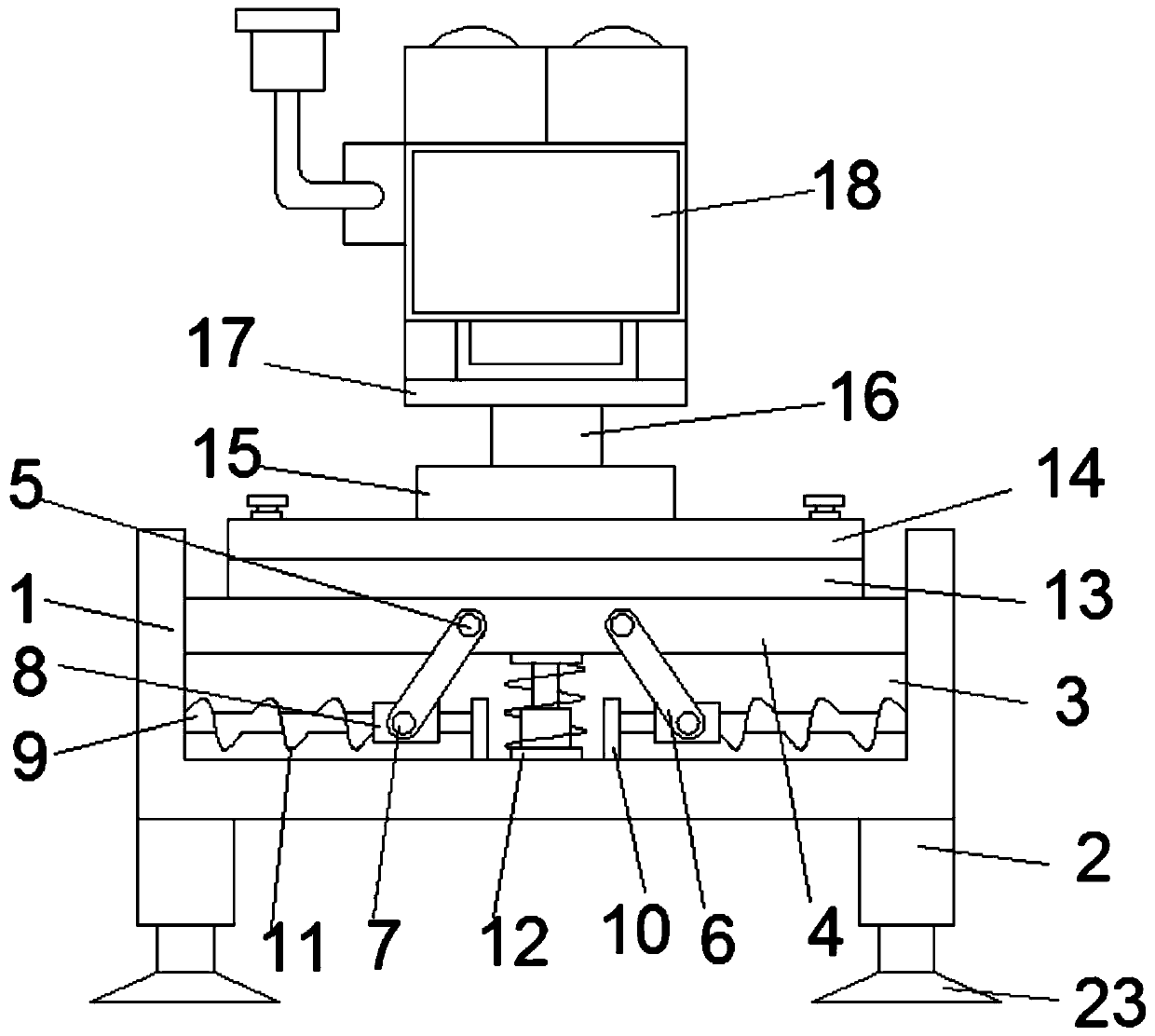
[0036] Such as Figure 1-3 As shown, a diesel engine with a base provided with a shock absorber according to an embodiment of the present invention includes a mounting base 1, the bottom of the mounting base 1 is symmetrically provided with shock absorbing columns 2, and the top of the mounting base 1 is provided with a shock absorbing groove. 3. A base 4 is provided in the damping groove 3, and a movable shaft-5 is symmetrically arranged on the base 4, and a support rod 6 is movably connected on the movable shaft-5, and the support rod 6 One end away from the movable shaft one 5 is sleeved on the movable shaft two 7, and the movable shaft two 7 is fixed on the slide block 8, and the slide block 8 is sleeved on the outside of the slide bar 9, and one end of the slide bar 9 is connected to the slide bar 9. The inner wall of the damping groove 3 is fixedly connected, and the other end of the sliding rod 9 is fixedly connected with the baffle plate 10. A shock absorbing spring 1...

Embodiment 2

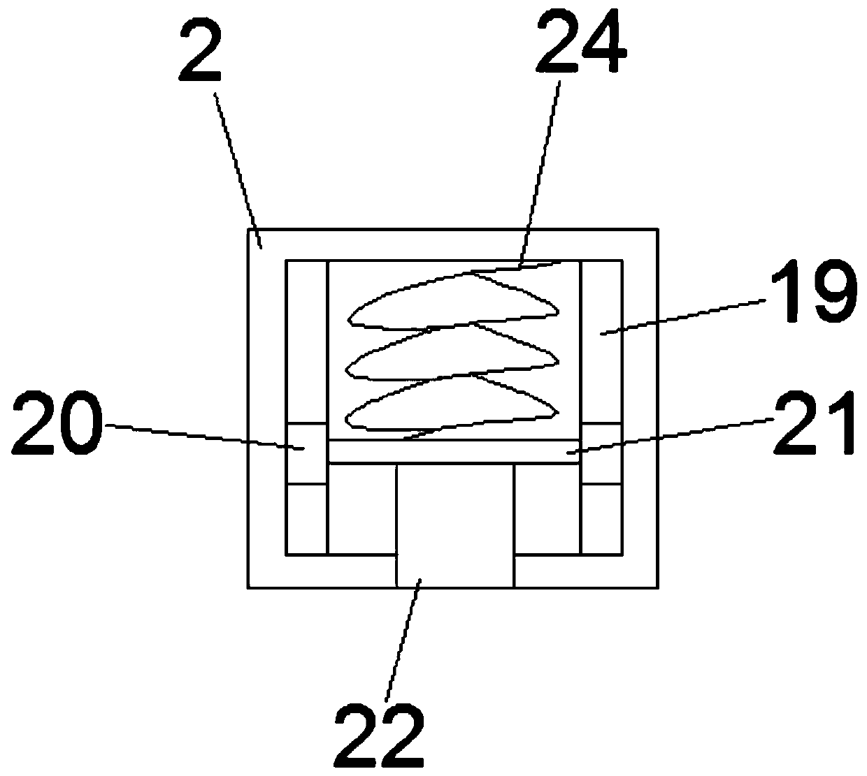
[0038] see Figure 1-3 , for the shock-absorbing column 2, the interior of the shock-absorbing column 2 is provided with a cavity, and the inside of the cavity is symmetrically provided with a limit groove 19, and the limit groove 19 is provided with a matching limit block 20 A limiting plate 21 is fixed between the limiting blocks 20 , and a supporting leg 22 is arranged at the bottom of the limiting plate 21 . As for the supporting leg 22 , the end of the supporting leg 22 away from the limiting plate 21 penetrates through the cavity and extends to the outside of the shock-absorbing column 2 to be provided with a non-slip pad 23 . For the limiting plate 21, a shock absorbing spring 2 24 is provided between the limiting plate 21 and the top of the cavity. With the cooperation of the bit plate 21 and the supporting legs 22, the anti-seismic performance of the mounting seat 1 is greatly improved.

Embodiment 3

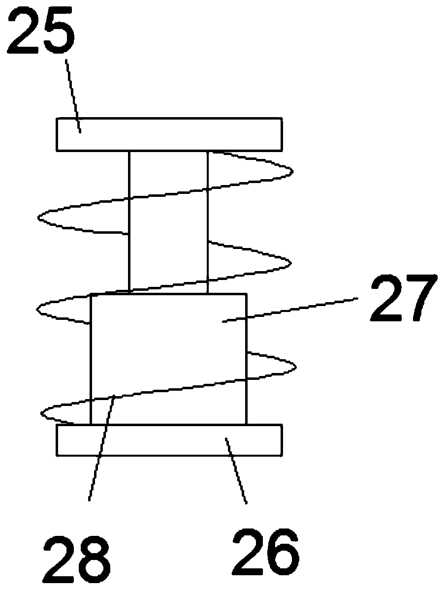
[0040] see Figure 1-3 , for the shock absorbing mechanism 12, the shock absorbing mechanism 12 includes an upper fixing plate 25 and a lower fixing plate 26, the upper fixing plate 25 is fixed on the bottom of the base 4, and the lower fixing plate 26 is fixed on the The bottom of the damping groove 3. For the upper fixed plate 25, a telescopic rod 27 is arranged between the upper fixed plate 25 and the lower fixed plate 26, and the telescopic rod 27 is located outside the upper fixed plate 25 and the lower fixed plate 26. The three shock absorbing springs 28 are set therebetween, and the shock absorbing springs two 24 further play a shock absorbing effect by being provided with the shock absorbing mechanism 12, so that the diesel engine 18 works more stably, thereby delaying the service life of the diesel engine 18 .

[0041] Such as Figure 1-4 As shown, according to another aspect of the present invention, a method for installing a diesel engine with a shock absorber on...


PUM

PropertyMeasurementUnit
Thicknessaaaaaaaaaa

Abstract

The invention discloses a diesel engine with a base provided with a shock absorber and an installation method of the diesel engine. The diesel engine comprises an installation seat. Shock absorption pillars are symmetrically arranged at the bottom of the installation seat. A shock absorption groove is formed in the top of the installation seat. A base is arranged in the shock absorption groove. First movable shafts are symmetrically arranged on the base, and supporting rods are movably connected to the first movable shafts. The ends, away from the first movable shafts, of the supporting rods are arranged on second movable shafts in a sleeving manner, and the second movable shafts are fixed to sliding blocks. The sliding blocks are arranged on the outer sides of sliding rods in a sleeving manner. One ends of the sliding rods are fixedly connected with the inner wall of the shock absorption groove, and the other ends of the sliding rods are fixedly connected with baffles. The baffles arefixed to the bottom of the shock absorption groove. First shock absorption springs are arranged at the positions, located between the baffles and the inner walls of the shock absorption grooves in asleeving manner, on the outer sides of the sliding rods. A shock absorption mechanism is arranged between the bottom of the base and the bottom of the shock absorption groove. A shock absorber cushionplate is arranged on the top of the base, and a shock absorber base is arranged on the top of the shock absorber cushion plate. The diesel engine has the beneficial effects that the shock absorptioneffect is obvious, meanwhile, the labor strength of installation is also lowered, the installation period is shortened, and the production efficiency is improved.

Description

technical field [0001] The invention relates to the field of mechanical installation engineering, in particular to a diesel engine with a base provided with a shock absorber and an installation method thereof. Background technique [0002] The advantages of diesel engines are high power and good economic performance. The working process of a diesel engine has many similarities with a gasoline engine. Each working cycle also goes through four strokes of intake, compression, power, and exhaust. However, since the fuel used in the diesel engine is diesel oil, its viscosity is higher than that of gasoline, it is not easy to evaporate, and its auto-ignition temperature is lower than that of gasoline, so the formation and ignition of combustible mixtures are different from those of gasoline engines. [0003] The base of the existing diesel engine has poor shock absorption performance. When it is working, it generates a lot of noise, which also affects the service life of the dies...

Claims


Application Information

Patent Timeline
IPC IPC(8): F16M11/04F16M11/22F16F15/067F16F15/02F02B77/00
CPCF02B77/00F16F15/02F16F15/067F16M11/043F16M11/22
Inventor 芮志英吴劼张恒汪娟娟张伟
Owner MAANSHAN CHANGLIFA MACHINERY MFG
Why Eureka
Try Eureka