Micro-expression recognition method and device

A recognition method and micro-expression technology, applied in the field of image recognition, can solve the problems of unreliable recognition results, inability to reflect the essence of micro-expressions, and inability to fully obtain micro-expression features, so as to reduce the redundancy of features and recognize micro-expressions. Precise results

Active Publication Date: 2020-06-12
GUANGDONG UNIV OF TECH
View PDF3 Cites 4 Cited by
  • Summary
  • Abstract
  • Description
  • Claims
  • Application Information

AI Technical Summary

Problems solved by technology

[0004] This application provides a micro-expression recognition method and device, which are used to solve the problem that the existing micro-expression recognition technology cannot fully obtain the characteristics of micro-expressions at all levels, and the obtained features contain redundant information that has nothing to do with expressions, which cannot reflect The nature of micro-expression, resulting in unreliable technical problems of recognition results

Method used


Image

  • Micro-expression recognition method and device
  • Micro-expression recognition method and device
  • Micro-expression recognition method and device

Examples


Embodiment 1

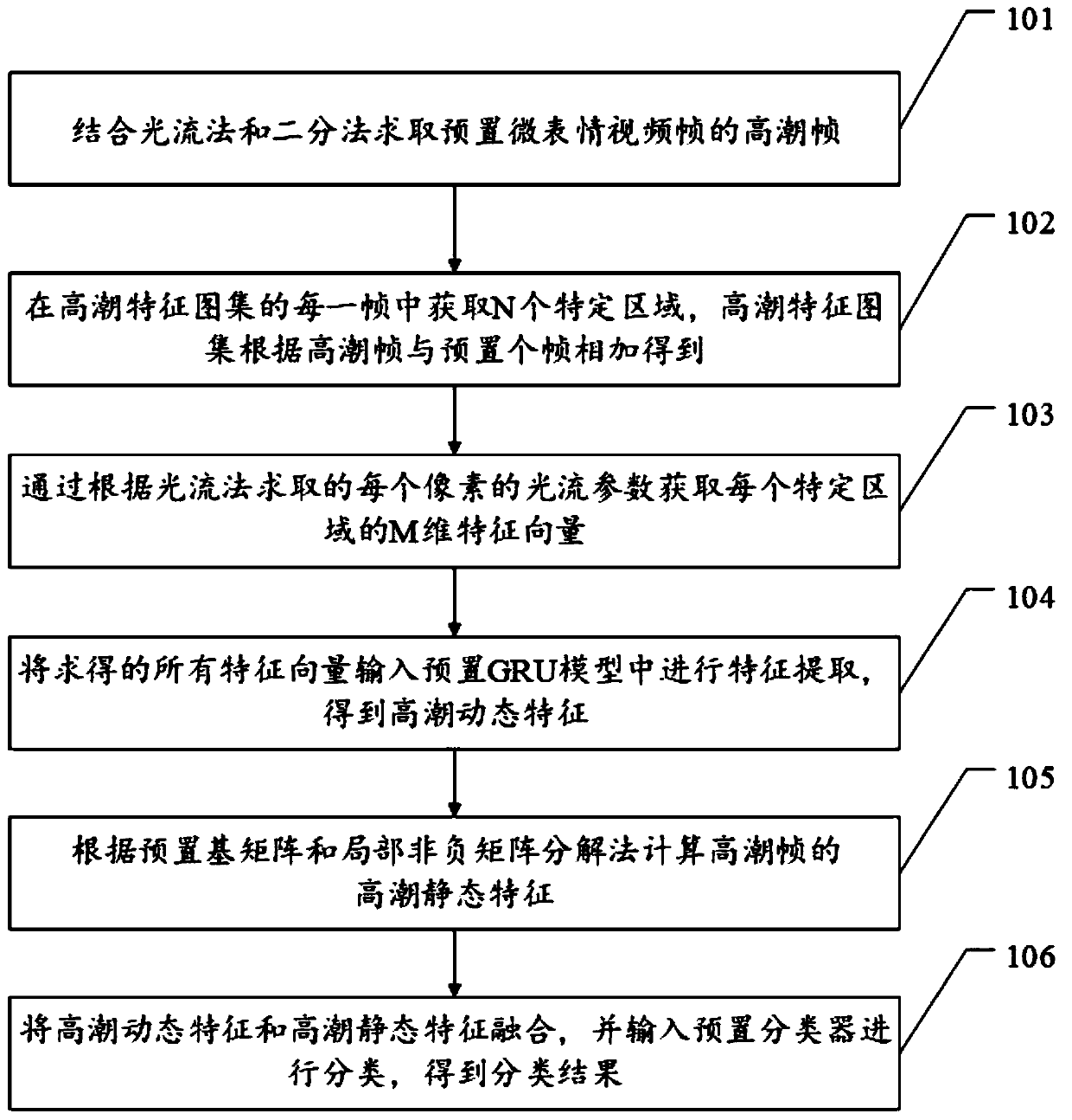
[0060] For ease of understanding, see figure 1 , Embodiment 1 of a micro-expression recognition method provided by the present application, including:

[0061] Step 101, combining the optical flow method and the dichotomy method to obtain the climax frame of the preset micro-expression video frame.

[0062] It should be noted that the optical flow method is a concept related to object motion detection in the field of view, and is used to describe the motion of the observation target, surface or edge caused by the motion of the observer. In this embodiment, the optical flow refers to the movement speed of corresponding pixels between two frames of images; the part of the expression in the micro-expression image that reacts most strongly, that is, the climax frame, can be accurately obtained by using the optical flow method. The preset micro-expression video frame is the micro-expression video obtained after some preprocessing, which is convenient for subsequent feature extract...

Embodiment 2

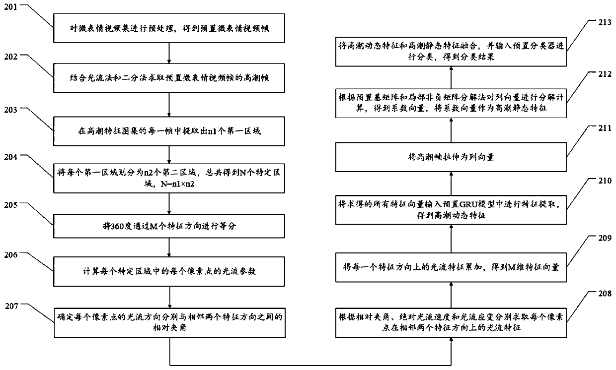
[0074] For ease of understanding, see figure 2 , Embodiment 2 of a micro-expression recognition method provided by the present application, including:

[0075] Step 201, preprocessing the micro-expression video set to obtain preset micro-expression video frames.


PUM


Abstract

The invention discloses a micro-expression recognition method and device. The method comprises the following steps: solving a climax frame of a preset micro-expression video frame by combining an optical flow method and a dichotomy; obtaining N specific regions in each frame of the high tide feature graph set, wherein the high tide feature graph set is obtained by adding high tide frames and preset frames; obtaining an M-dimensional feature vector of each specific region through an optical flow parameter of each pixel obtained according to an optical flow method; inputting all the obtained feature vectors into a preset GRU model for feature extraction to obtain high tide dynamic features; calculating high tide static characteristics of the high tide frame according to a preset basis matrixand a local non-negative matrix factorization method; and fusing the high tide dynamic features and the high tide static features, and inputting the fused features into a preset classifier for classification to obtain a classification result. According to the method and the device, the technical problem of unreliable identification result caused by the fact that the existing micro-expression identification technology cannot completely obtain the characteristics of each layer of the micro-expression and has redundant information irrelevant to the expression is solved.

Description

technical field [0001] The present application relates to the technical field of image recognition, in particular to a micro-expression recognition method and device. Background technique [0002] The modernization of industry and the rapid development of intelligence have made robot technology more mature, making it more common for robots and people to assist in the work scene. When designing a human-computer interaction system for a robot, in order to evaluate the effect of human-computer interaction, physical In the experiment, the experimenter and the robot cooperate to complete some tasks. After the experiment, the experimenter needs to fill in the questionnaire, analyze the results, obtain conclusions, and carry out corresponding analysis to transform the robot control strategy. In order to enable the robot to perceive the surrounding environment, devices such as microphones and cameras are usually installed on the robot, so that the robot can understand human commands...

Claims


Application Information

Patent Timeline
Patent Type & Authority Applications(China)
IPC IPC(8): G06K9/00G06K9/62
CPCG06V40/168G06V40/174G06F18/2133G06F18/241Y02A90/10
Inventor 陈华俊高军礼蔡吉轮
Owner GUANGDONG UNIV OF TECH
Why Eureka
Try Eureka