
Method for producing one or more concave cut-outs on a main body which is, in particular, substantially cylindrical, armature, keeper plate, and electromagnetic actuator

An electromagnetic actuator and retaining plate technology, which is applied in the manufacture of electromagnets with armatures, electromagnets, inductors/transformers/magnets, etc., can solve the problem of impossible secondary processing, separate milling, and inability to use through-grinding process and other issues to achieve the effect of horizontal precision and high horizontal precision

Inactive Publication Date: 2020-06-12
KENDRION VILLINGEN GMBH
View PDF11 Cites 4 Cited by
  • Summary
  • Abstract
  • Description
  • Claims
  • Application Information

AI Technical Summary

Problems solved by technology

These grooves are usually straight and therefore cannot be machined subsequently using the through-grinding process
Milling slots must be milled and deburred using small end mills, however, this only allows limited feed
The lathe must be stopped at this point, which means parallel secondary machining is not possible
Additionally, each slot must be milled individually

Method used


Image

  • Method for producing one or more concave cut-outs on a main body which is, in particular, substantially cylindrical, armature, keeper plate, and electromagnetic actuator
  • Method for producing one or more concave cut-outs on a main body which is, in particular, substantially cylindrical, armature, keeper plate, and electromagnetic actuator
  • Method for producing one or more concave cut-outs on a main body which is, in particular, substantially cylindrical, armature, keeper plate, and electromagnetic actuator

Examples


Embodiment Construction

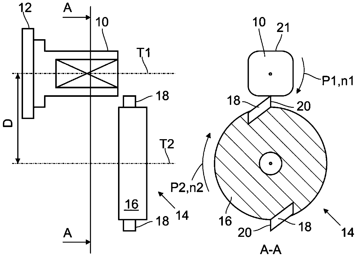
[0051] figure 1 The polygon turning known from the prior art is shown on the basis of a schematic diagram. Here, the substantially cylindrical body 10 in the initial state is clamped in a lathe 12 and rotated at a first rotational speed n1 about a first rotational axis T1 . Furthermore, the turning tool 14 has a disc-shaped receiving body 16 to which two high-speed cutting tools are fixed, rotating at a second rotational speed n2 about a second rotational axis T2. The second axis of rotation T2 extends parallel and is offset by a distance D from the first axis of rotation T1. The main body 10 rotates in a first rotational direction, while the turning tool 14 rotates in a second rotational direction, which is indicated by arrows P1 and P2. based on figure 1 In the illustration selected in , the main body 10 and the turning tool 14 are rotated to the right. The distance D between the first axis of rotation T1 and the second axis of rotation T2 is selected such that the high ...


PUM


Abstract

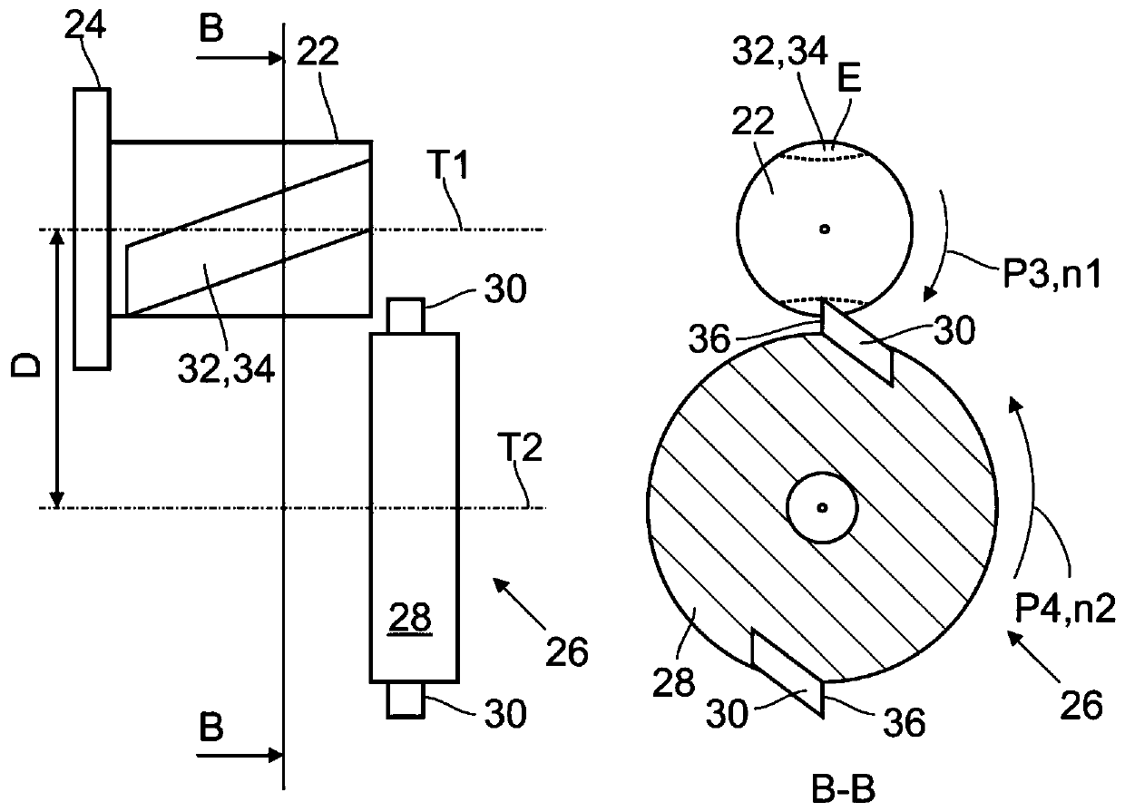
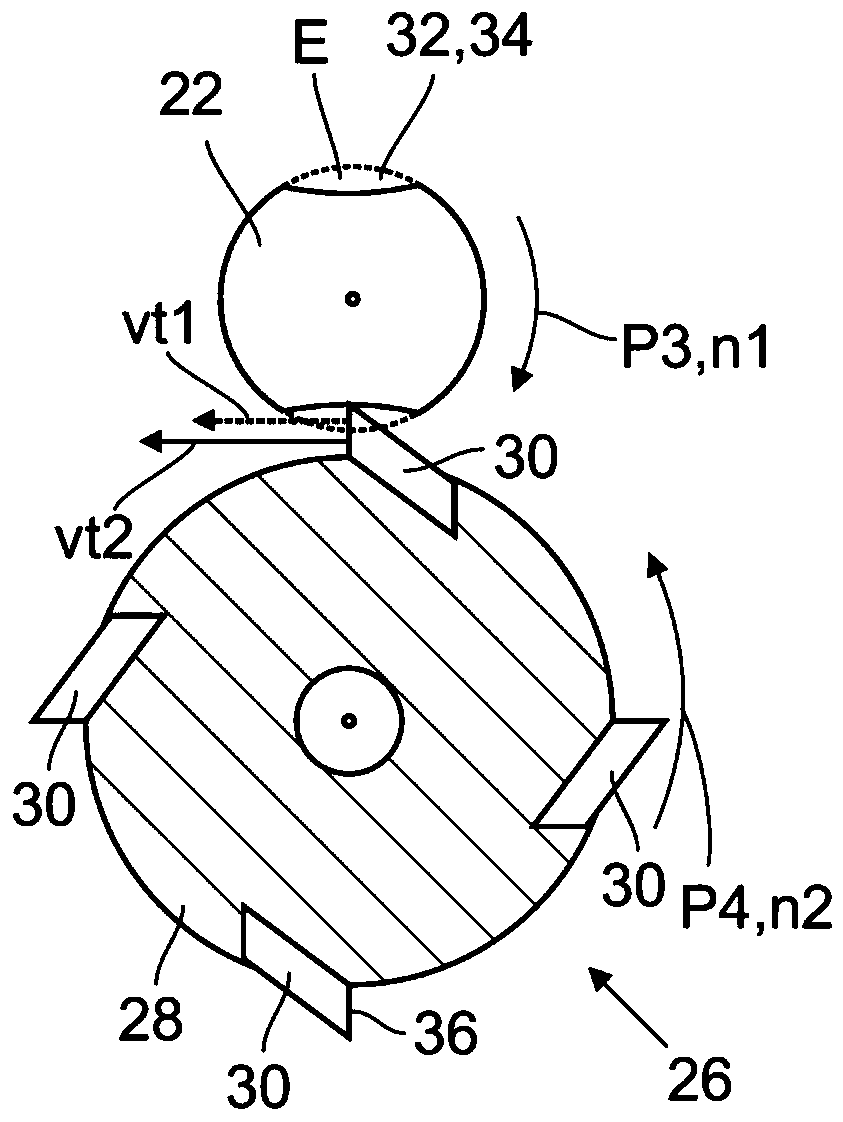
The present invention relates to a method for producing one or more concave cut-outs (32) on a main body (22) which is, in particular, substantially cylindrical, more particularly for producing one ormore grooves (34) on an armature (40), a push rod (72), or a magnetic keeper plate, comprising the following steps: providing a substantially cylindrical main body (22) having a first axis of rotation (T1), rotating the cylindrical main body (22), by means of a lathe (24), about the first axis of rotation (T1) in a first rotational direction, and rotating a striking tool (26), provided witha number of fly cutters (30), about a second axis of rotation (T2) in a second rotational direction opposite to the first direction, said second axis running parallel and offset to the first axis ofrotation (T1), so that the fly cutter (30) engages stock-removably with the main body (22) in order to produce the cut-out (32). The invention also relates to an armature, a push rod and a magnetic keeper plate, having one or more cut-outs produced according to this method, and to an electromagnetic actuator comprising an armature of this type or a keeper plate of this type.

Description

technical field [0001] The invention relates to a method for producing one or more grooves, in particular on an armature, a push rod or a retaining plate, said armature, push rod or A retaining plate, and an electromagnetic actuator with such an armature or such a retaining plate. Background technique [0002] Electromagnetic actuators are characterized in that they comprise an armature which can be moved at least between a first position and a second position by energizing the coil unit. Such electromagnetic actuators are widely used in valves where they block the flow of fluid in a first position and release fluid in a second position. For example, a valve seat can be opened and closed with a push rod actuated by such an actuator. A corresponding actuator is disclosed in DE 10 2014 113 349 A1. [0003] In many cases, the armature is movably mounted along a longitudinal axis in guide means such as guide tubes or slide bearings. In some cases, the armature is also arrang...

Claims


Application Information

Patent Timeline
Patent Type & Authority Applications(China)
IPC IPC(8): B23C3/30B23C3/32B23P13/02F16K27/02F16K31/06H01F7/08H01F7/16H01F41/02
CPCB23C3/30B23C3/32F16K27/029F16K31/0693B23P13/02H01F7/081H01F7/1607H01F7/1615H01F41/0206H01F2007/086B23B5/48
Inventor R·赫曼
Owner KENDRION VILLINGEN GMBH
Learn More