Lift pin holder

A technology of lifting pins and retainers, which is applied in semiconductor/solid-state device manufacturing, discharge tubes, electrical components, etc.

Pending Publication Date: 2020-06-12
APPLIED MATERIALS INC
View PDF7 Cites 0 Cited by
  • Summary
  • Abstract
  • Description
  • Claims
  • Application Information

AI Technical Summary

Problems solved by technology

However, because the cleaning did not fix the underlying problem, the debris again fell into the liftpin retainer

Method used


Image

  • Lift pin holder
  • Lift pin holder
  • Lift pin holder

Examples


Embodiment Construction

[0018] Embodiments of lift pin retainers and lift pin assemblies including the same are disclosed herein. The inventive lift pin retainer advantageously reduces or eliminates the problems of conventional lift pin retainers that cause the lift pin retainer to become jammed due to debris falling into the lift pin retainer. The inventive liftpin retainer eliminates sharp edges that could come into contact with debris falling into the liftpin retainer, thus significantly reducing the risk of elements of the liftpin retainer becoming caught by debris. The inventive lift pin retainer further improves lift pin stability by providing additional support to secure the lift pin within the lift pin retainer.

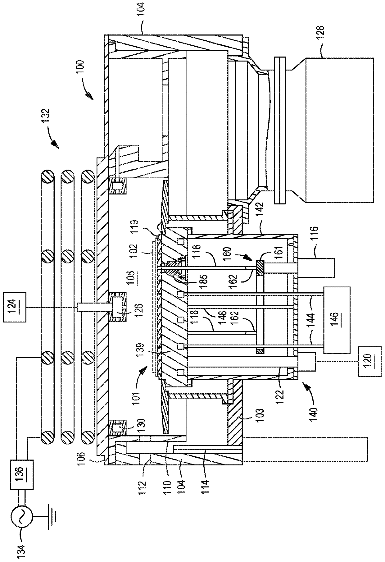
[0019] figure 1 A schematic cross-sectional view is depicted of an illustrative substrate processing chamber 100 in which a liftpin holder and liftpin assembly according to some embodiments of the present disclosure may be used. Suitable reactors that may be adapted for use with t...


PUM


Abstract

Embodiments of lift pin holders are disclosed herein. In some embodiments, a lift pin holder includes a housing member having an upper portion and a lower portion, wherein the upper portion includes an annular wall defining a central space; a support member disposed at least partially within the central space and having a base and an upwardly protruding portion configured to support a lift pin; afirst gripper disposed atop the support member and having a first plurality of prongs protruding upward from a body of the first gripper and configured to grip the lift pin; and a second gripper disposed atop the base of the support member and having a second plurality of prongs protruding upward from a body of the second gripper and are configured to grip the lift pin, wherein the first gripper is disposed within the third central opening.

Description

technical field [0001] Embodiments of the present disclosure generally relate to substrate processing. Background technique [0002] In semiconductor processing, lift pins are used to raise and lower a semiconductor substrate onto a substrate support in a process chamber. Typically, a robotic arm transfers the substrate into an upper portion of the process chamber where the substrate rests on lift pins that extend upward through the substrate support. The lift pins are then lowered into the lower portion of the process chamber to place the substrate on the substrate support. Thereafter, the robotic arm is withdrawn from the chamber. [0003] After the substrate has been processed, the lift pins are raised up through bushings in the substrate support to lift the substrate off the substrate support by pushing up against the substrate. The robotic arm is then reinserted under the substrate to evacuate the processed substrate from the chamber. The inventors have found that c...

Claims


Application Information

Patent Timeline
IPC IPC(8): H01L21/687H01L21/683
CPCH01L21/68742H01J37/32724H01J37/32733H01J2237/022H01J2237/2007H01L21/68707H01L21/683H01L21/67069B23Q7/005H01J2237/20235
Inventor K·K·恩古耶
Owner APPLIED MATERIALS INC
Why Eureka
Try Eureka