Clamping jaw mechanism controlled by servo electric cylinder

A servo electric cylinder and gripper technology, applied in the field of robotics, can solve the problems of falling, deformation of the object to be clamped, and shaking of the object to be clamped, etc., to achieve the effect of improving applicability, improving stability, and avoiding shaking

Inactive Publication Date: 2020-06-16
张梅
View PDF9 Cites 11 Cited by
  • Summary
  • Abstract
  • Description
  • Claims
  • Application Information

AI Technical Summary

Problems solved by technology

[0003] When the gripper mechanism of the existing robot is in use, the object to be grasped needs to be placed in a designated position first, and then the gripper mechanism at the front end of the robot stretches out in the direction of the object to be grasped and grasped. However, due to the existing The clamping jaw mechanism cannot accurately control the size of the clamped object, so that the clamped case is too large or too small. When the clamping force is too large, the object to be clamped will be deformed, and the clamping If the force is too small, it will cause the object to be clamped to shake or even fall when clamping. Secondly, when the existing clamping jaw mechanism is clamping, it will stick to the contact position between the clamping jaw mechanism and the object to be clamped. The rubber pad is connected to avoid the wear of the object to be clamped and ensure the stability of the grasping. However, due to the different shapes of the surface of the object to be clamped, the jaw mechanism cannot be tightly connected to the surface of the object to be clamped when clamping. Therefore, we propose a gripper mechanism controlled by a servo electric cylinder.

Method used


Image

  • Clamping jaw mechanism controlled by servo electric cylinder
  • Clamping jaw mechanism controlled by servo electric cylinder
  • Clamping jaw mechanism controlled by servo electric cylinder

Examples


Embodiment Construction

[0025] The present invention will be further described in detail below in conjunction with the drawings.

[0026] The same parts are indicated by the same reference numerals. It should be noted that the words "front", "rear", "left", "right", "upper" and "lower" used in the following description refer to the directions in the drawings, and the words "bottom" and "top" "Face", "inner" and "outer" respectively refer to directions toward or away from the geometric center of a particular component.

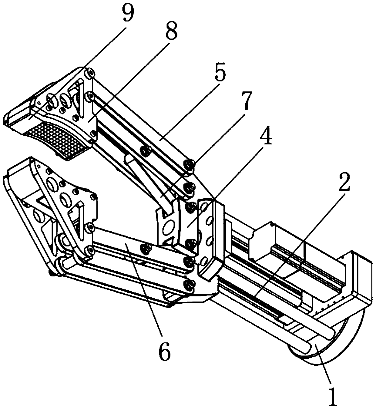
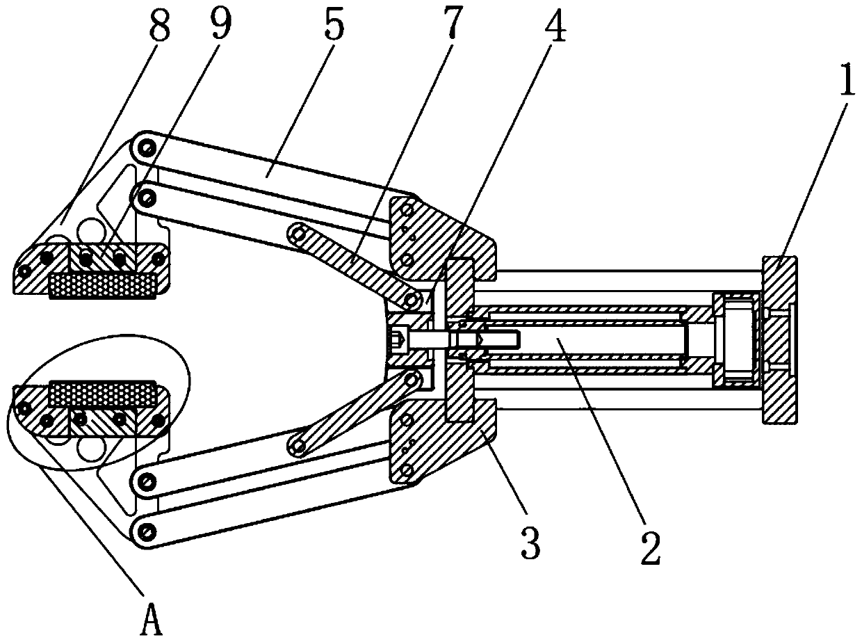
[0027] Reference Figure 1-4 As shown, a clamping jaw mechanism controlled by a servo electric cylinder includes a clamping jaw fixing base 1 and a motor base 3 for connecting with a robot, and a support rod is arranged between the clamping jaw fixing base 1 and the motor base 3 near the edge An electric cylinder 2 is fixedly installed between the clamping jaw fixing base 1 and the motor base 3, and the top of the electric cylinder 2 is equipped with a moving bracket 4, and both sides of...


PUM


Abstract

The invention discloses a clamping jaw mechanism controlled by a servo electric cylinder. The clamping claw mechanism comprises a clamping jaw fixing base and a motor base, wherein an electric cylinder is fixedly arranged between the clamping jaw fixing base and the motor base; a movable bracket is arranged at a top end of the electric cylinder; first connecting rods and second connecting rods aresymmetrically arranged on both sides of the motor base; front clamping pieces are arranged between other ends of the first connecting rod and the second connecting rod on the same side; rubber blocksare arranged on opposite outer surfaces of the two clamping pieces; air bags are embedded into top ends of the rubber blocks; and pressure sensors are arranged inside the front clamping pieces. According to the clamping jaw mechanism controlled by the servo electric cylinder disclosed by the invention, pressure sensors are arranged at back ends of the rubber blocks, and can be used for detectingthe pressure on the surface of an object to be clamped by the rubber blocks, so that the situation of over large or over small clamping force is avoided. Moreover, the air bags are arranged at the front ends of the rubber blocks, and nickel-titanium meshes are arranged inside the rubber blocks, so that the clamping jaw mechanism can fit closely with the surfaces of the objects of different shapesto be clamped, and the adaptability of the device is improved.

Description

Technical field [0001] The invention relates to the technical field of robots, in particular to a clamping jaw mechanism controlled by a servo electric cylinder. Background technique [0002] With the development of science and technology, robots continue to enter people's lives and improve all aspects of people's lives, such as replacing manual labor with high-intensity repetitive tasks, or performing precise grasping and placing; [0003] When the gripper mechanism of the existing robot is used, the object to be grasped needs to be placed at a designated position, and then the gripper mechanism on the front end of the robot extends to the direction of the object to be grasped and grasps. However, due to the existing The clamping jaw mechanism is unable to precisely control the size of the clamping case, so that the clamping case is too large or too small. If the clamping force is too large, the object to be clamped will be deformed. If the force is too small, the object to be cl...

Claims


Application Information

Patent Timeline
Patent Type & Authority Applications(China)
IPC IPC(8): B25J15/02B25J15/08B25J15/12B25J19/00B25J13/08
CPCB25J13/085B25J15/022B25J15/08B25J15/12B25J19/00
Inventor 徐汉元张梅
Owner 张梅
Why Eureka
Try Eureka